TM-9-2350-311-10 - Page 713 of 775
TM 9-2350-311-10
G-3 LUBRICATION INSTRUCTIONS — CONTINUED
4.
POWER PACK ASSEMBLY RESERVOIR (C)
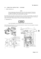
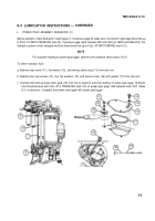
Before operation, check fluid level in sight gage (7). If pressure gage (8) reads zero, fluid level in sight gage should be up
to FULL AT ZERO PRESSURE mark (9). If pressure gage reads between 925 and 1225 psi (6378 and 8446 kPa), the
hydraulic system is fully charged and fluid level should be up to FULL AFTER PUMPING mark (10).
NOTE
For accurate reading on power pack gage, perform zero pressure check (para 3-6.4).
To check hydraulic fluid:
a. Remove cap screw (11), flat washer (12), and towing cable strap (13) from cab roof.
b. Remove four cap screws (14), four flat washers (15), and access cover (16) with gasket (17) from cab roof.
c. Unscrew and remove power pack gage (18) from top of reservoir and note reading on power pack gage. Hydraulic
fluid should be level with FULL AT 0 PRESSURE mark (19) on power pack gage. Add hydraulic fluid, OHT (Table
G-1) to reservoir, if needed, and check level again with power pack gage.
G-9
Back to Top


