TM-9-2350-311-20-1 - Page 1183 of 1275
TM9-2350-311-20-1
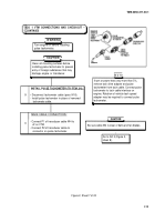
M109 VEHICLE TEST CARD — VID 11 ADDITIONAL TEST CONNECTIONS
ALTERNATOR TESTS — M109A2/M109A3
NOTE
Picture shows conduction-cooled rectifier. Tests also apply to alternator cable in
vehicles with fan-tooted rectifier.
NOTE
Perform the following teats with the alternator cable disconnected as shown.
Test 91, stator resistance measured from pin A to B, B to C, and A to C of alternator cable must
be less than 5 ohms with engine off.
Test 92, stator insulation measured from pin A to ground, B to ground, and C to ground, 9.9.9.9
with engine off.
Teat 93, alternator output volts, measured from pin A to B, B to C, and A to C, with engine idling
and with 12 Vdc applied to pin D, and with pin E grounded, 30 to 34 Vac at idle.
WARNING
When performing teat 93,
do not run engine above
idle with voltage applied on
pins D and E. Equipment
damage and personal injury
may result.
NOTE
Perform the following teat with the alternator cable connected to the regulator and the
current probe positioned as shown. Be sure the probe is 10 in. (25.4 cm) or more
away from other wires.
Test 90, alternator output current, 30 amps minimum at 1000 to 1200 rpm (accessories on and
partially discarged).
ALTERNATOR TESTS — M109A4/M109A5
NOTE
Perform the following teats with the altenator cable disconnected as shown.
Test 91, stator resistance measured from pin B to D, D to F, and B to F of alternator cable must
be baa than 5 ohms with engine off.
Teat 92, stator insulation measured from pin B to ground, D to ground, and F to ground 9.9.9.9
with engine off.
Teat 93, alternator output wits, measured from pin B to D, D to F, and B to F, with engine idling
and with 12 Vdc applied to pin A, and with pin C gournded, 30 to 34 Vac at idle.
WARNING
When performing teat 93,
do not run engine above
idle with voltage applied on
pins D and E. Equipment
damage and personal injury
may result.
NOTE
Perform the following teat with the alternator cable connected to the regulator and the
currant probe positioned as shown. Be sure the probe is 10 in. (25.4 cm) or more away
from other wires.
Test 90, alternator output current, 30 amps minimum at 1000 to 1200 rpm (accessories on and
partially discarged).
NOTE
Starting and charging
circuits are in Chapter 3
(TM 9-2350-311-20-1).
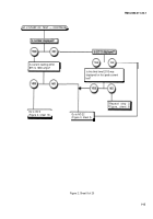
Figure 1, Sheet 2 of 2
I-6
Back to Top


