TM-9-2350-311-20-1 - Page 1185 of 1275
TM9-2350-311-20-1
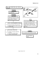
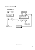
GO 1 VTM CONNECTIONS AND CHECKOUT
CONTINUED
1
2
CONNECT BATTERY TO VTM:
.
- PULL OFF VTM power switch.
.
Connect PI of power cable W5 to J1 on VTM.
- Connect red clip El of cable W5 to positive
terminal of M109A2/A3/A4/A5 battery.
- Connect black clip E2 of cable W5 to negative
terminal of M109A2/A3/A4/A5 battery.
Make sure all connections are
correct and secure.
POWER UP.
.
- PUSH ON VTM power switch.
- Verify that display indicates .8.8.8.8 for
approximately 2 seconds and then
changes to -----
Does the VTM display .8.8.8.8 and then
change to --- -?
NOT E
Aline white mark
on connector P1
with large slot in
keyway of J1.
Twist locking
ring until it clicks.
If only a portion of .8.8.8.8 or
---- is displayed, a display
module may be burned out.
Refer to TM 9-4910-571-12&P
for module replacement.
- Set power switch to PULL OFF.
- Check W5 for proper connections. Red
clip El on positive terminal, black clip E2
on negative terminal.
- Check and clean all battery connections
and interconnecting cables.
- PUSH ON VTM power switch.
1
Does VTM display .8.8.8.8 and then
change to- -- -?
Go to step 4,
Go to step 3,
Figure 2, sheet 4.
Figure 2, sheet 3.
Figure 2, Sheet 2 of 20
I-8
NOTE
Back to Top

