TM-9-2350-311-20-1 - Page 274 of 1275
TM 9-2350-311-20-1
3-3
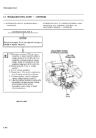
TROUBLESHOOTING CHART — CONTINUED
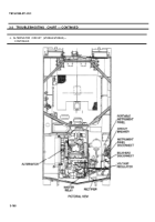
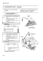
n. ALTERNATOR CIRCUIT (M109A4/M109A5) —
ALTERNATOR FAILS TO CHARGE BATTERIES; GAGE
CONTINUED
INDICATION: NOT CHARGING, UNSTEADY OR
INACCURATE READING — CONTINUED
CONTINUED FROM STEP A
I
NOTE
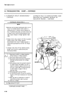
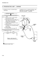
For steps H, 1, J, and K use heavy jumper wires with
alligator clips.
I
. . .
.
3.
4.
5.
6.
7.
8.
9.
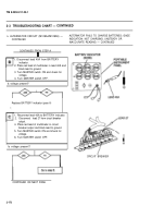
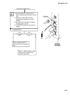
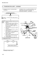
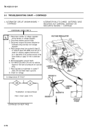
Disconnect powerplant wiring harness from
alternator.
Place jumper wires from pin C (lead 3) of
alternator to battery negative terminal and
pin A (lead 1) of alternator to positive
terminal of same battery to apply 12 Vdc
to alternator field.
Place a jumper wire from pin E to socket E
(lead 503).
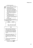
Turn MASTER switch ON and run vehicle
engine at 1000 rpm.
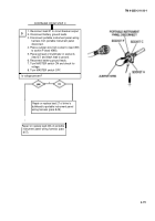
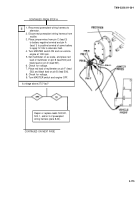
Set multimeter on ac scale, and place red
lead of multimeter on pin B (lead 500) and
black lead on pin D (lead 501).
Check for voltage.
Place red lead of multimeter on pin F (lead
502) and black lead on pin B (lead 500).
Check for voltage.
Turn MASTER switch and engine OFF.
Is voltage above 27.5 Vat?
Replace alternator (para 8-2).
CONTINUED ON NEXT PAGE
3-174
Back to Top

