TM-9-2350-311-20-1 - Page 264 of 1275
TM 9-2350-311-20-1
3-3
TROUBLESHOOTING
CHART — CONTINUED
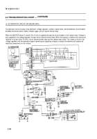
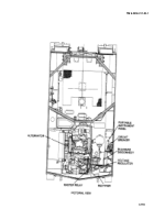
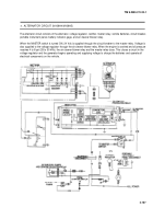
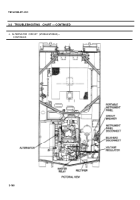
m. ALTERNATOR CIRCUIT (M109A2/M109A3)—
ALTERNATOR FAILS TO CHARGE BATTERIES; GAGE
CONTINUED
INDICATION: NOT CHARGING, UNSTEADY OR
INACCURATE READING — CONTINUED
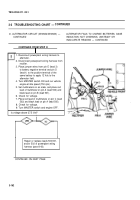
CONTINUED FROM STEP K
NOTE
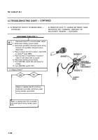
• Batteries can be totally discharged within 4 to 6
hours if air cleaner blower motor system is
malfunctioning or if blower motors operate full
time. Troubleshooting step L provides a basic test
of blower motor circuit by testing blower motor
relay output voltage to voltage regulator (lead
27B).
• If blower motor relay output is 24 Vdc or greater
(battery power) with voltage regulator
disconnected from circuit, voltage regulator is
malfunctioning/inoperative and will not charge
battery.
• If voltage is less than 24 Vdc (battery power),
blower motor circuit is malfunctioning and
discharging battery.
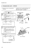
I
L
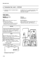
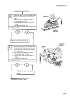
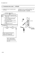
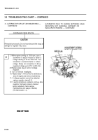
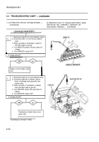
1. Reconnect rectifier to voltage regulator
wiring harness to voltage regulator.
2. Disconnect battery ground leads.
3. Disconnect engine disconnect bracket-to-
bulkhead wiring harness from voltage
regulator.
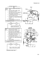
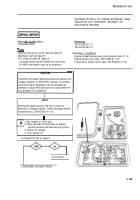
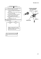
4. Place jumper wires from socket A (lead 2)
to socket B (lead 400-459B), from pin C
(lead 3) to battery negative terminal, and
from pin F (lead 27B) to positive terminal
of same battery to apply 12 Vdc to
alternator field.
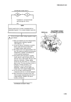
5. Reconnect battery ground leads.
6. Turn MASTER switch ON and run vehicle
engine at 1000 rpm (oil pressure at 12 psi [83
kPa]).
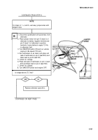
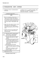
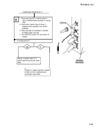
7. Place red lead of multimeters in socket F
(lead 27B) and black lead to ground.
8. Check for voltage.
Is voltage above 27.5 Vdc?
I
CONTINUED ON NEXT PAGE
3-164
Back to Top

