TM-9-2350-311-20-1 - Page 261 of 1275
TM 9-2350-311-20-1
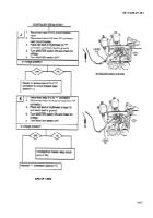
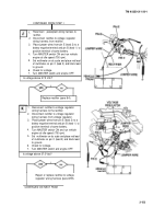
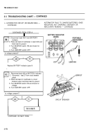
CONTINUED FROM STEP A
NOTE
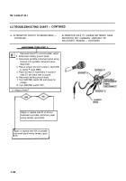
For steps H, 1, J, and K, use heavy jumper wires with
alligator clips.
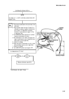
1. Disconnect powerplant wiring harness from
alternator.
2. Place jumper wires from pin E (lead 3) of
alternator to battery negative terminal and
pin D (lead 1) of alternator to positive
terminal of same battery to apply 12 Vdc
to alternator field.
3. Turn MASTER switch ON and run vehicle
engine at idle speed (750 rpm).
4. Set multimeters on ac scale, and place red
lead of multimeters on pin A (lead 500) and
black lead on pin B (lead 501).
5. Check for voltage.
6. Place red lead of multimeters on pin C (lead
502) and black lead on pin A (lead 500).
7. Check for voltage.
8. Turn MASTER switch and engine OFF.
Is voltage above 27.5 Vdc?
I
Replace alternator (para 8-2).
CONTINUED ON NEXT PAGE
3-161
Back to Top

