TM-9-2350-311-20-1 - Page 256 of 1275
TM 9-2350-311-20-1
3-3
TROUBLESHOOTING
CHART — CONTINUED
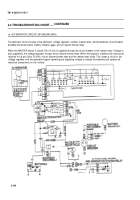
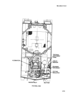
m. ALTERNATOR CIRCUIT (M109A2/M109A3) —
ALTERNATOR FAILS TO CHARGE BATTERIES; GAGE
CONTINUED
INDICATION: NOT CHARGING, UNSTEADY OR
INACCURATE READING
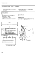
INITIAL SETUP
Configurations
.
References
M109A2/M109A3
TM 9-2350-311-10
TM 9-6140-200-14
T
O
oI
S
General mechanic’s tool kit (item 64,
Appx H)
.
Equipment Conditions
Multimeters (item 36, Appx H)
Engine compartment access cover removed (para 11-5)
TA-1 probe kit (item 43, Appx H)
Engine access door open
(TM 9-2350-311-10)
(Long test leads may be needed for some tests;
Transmission access doors open (TM 9-2350-311-1 0)
16 AWG wire may be used as an extension.)
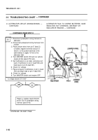
CAUTION
I
Extremely low battery electrolyte levels will cause a low
voltage indication on BATTERY indicator on portable
instrument panel. Regulators can be damaged by
attempts to adjust rheostat beyond its stops when the
only problem is dry batteries.
NOTE
Vehicle idle speed must be 750 rpm in order for
alternator to charge properly. Check idle speed before
troubleshooting (TM 9-2350-311-10).
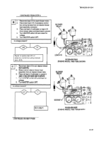
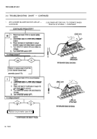
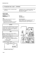
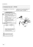
1. Run engine at 1000 rpm.
2. Place red lead of multimeters on battery
positive terminal and black lead to ground.
3. Check for voltage.
4. Turn engine off.
Is voltage 27.5 Vdc or higher?
I
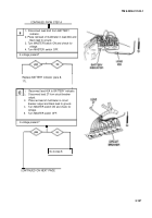
CONTINUED ON NEXT PAGE
3-156
Back to Top

