TM-9-2350-311-20-1 - Page 254 of 1275
TM
9-2350-311-20-1
3-3 TROUBLESHOOTING CHART —
CONTINUED
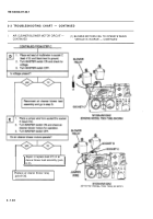
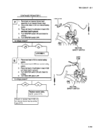
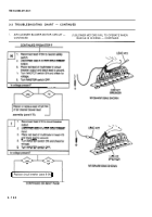
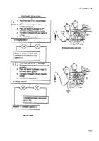
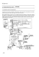
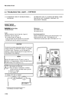
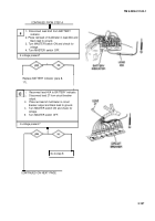
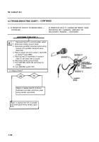
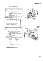
m. ALTERNATOR CIRCUIT (M109A2/M109A3)
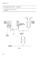
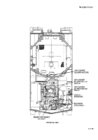
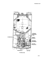
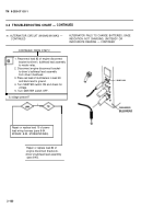
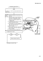
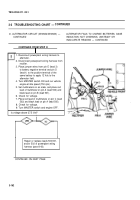
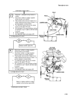
The alternator circuit consists of the alternator, voltage regulator, rectifier, master relay, vehicle batteries, circuit breaker,
portable instrument panel, battery indicator gage, and air cleaner blower relay.
When the MASTER switch is turned ON, 24 Vdc is supplied through the circuit breaker to the master relay. Voltage is
also supplied to the voltage regulator through the air cleaner blower relay. When the engine is cranked and oil pressure
reaches 4 to 8 psi (28 to 55 kPa), the air cleaner blower relay and the master relay close. This closes a circuit in the
voltage regulator and the generator begins operating and supplying voltage to charge the batteries and operate all
electrical components on the vehicle.
3-154
Back to Top

