TM-9-2350-311-20-1 - Page 252 of 1275
TM 9-2350-311-20-1
3-3
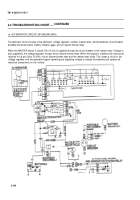
TROUBLESHOOTING CHART — CONTINUED
1.
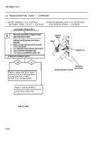
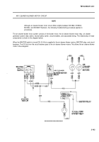
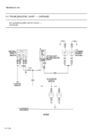
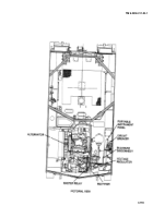
AIR CLEANER BLOWER MOTOR CIRCUIT —
(2) ONE BLOWER MOTOR FAILS TO OPERATE
CONTINUED
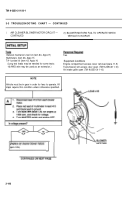
INITIAL SETUP
General mechanic’s tool kit (item 64, Appx H)
Multimeters (item 36, Appx H)
TA-1 probe kit (item 43, Appx H)
I
Required
Two
t
Conditions
Engine compartment access cover removed (para 11-5)
Transmission left access door open (TM 9-2350-311-10)
Air intake grille open (TM 9-2350-311-10)
NOTE
Vehicle must be in neutral for the following step.
N
A
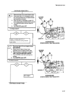
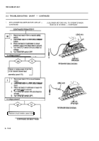
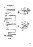
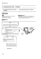
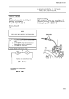
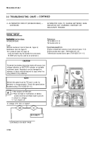
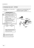
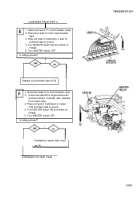
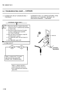
1. Disconnect lead 415 from disabled blower
motor.
.
2. Place red lead of multimeters in lead 415 and
black lead to ground.
3. Turn MASTER switch ON and check for
voltage.
4. Turn MASTER switch OFF.
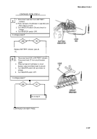
Is voltage present?
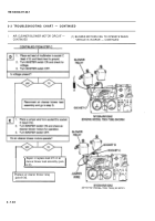
Replace air cleaner blower motor
(para 8-36).
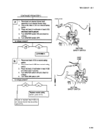
accessory control box to heater/
blower wiring harness (para 8-52).
END OF TASK
3-152
Repair or replace lead 415 of
Back to Top

