TM-9-2350-311-20-1 - Page 482 of 1275
TM 9-2350-311-20-1
4-5 POWERPLANT — CONTINUED
a. Removal — Continued
29
30
31
32
33
34
35
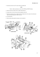
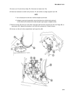
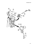
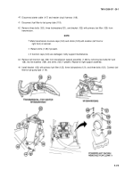
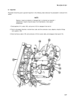
Disconnect four electrical connectors (86) at master relay (87) and voltage regulator (88).
NOTE
Step
30
applies only to M109A2/M109A3 Howitzers.
Remove screw (89) and two Iockvvashers (90) and disconnect powerplant ground cable (91). Install
Iockwashers and screw.
Move throttle control to full open position, pull out quick-release pin (92), and release throttle governor control
rod (93).
Tag tachometer and speedometer flexible driveshafts (94 and 95). Unscrew two nuts (96) and disconnect
driveshafts.
Unscrew nut (97) and disconnect throttle valve control rod (98).
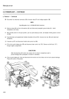
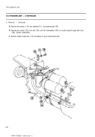
Pull out two quick-release pins (99) and disconnect steer control rod (100). Remove rod with boot (101 )
through engine compartment.
CAUTION
After disconnecting shift control rod, ensure rod is in driver’s compartment wall to
prevent damage when powerplant is hoisted or reinstalled,
Pull out quick-release pin (102) and disconnect shift control rod (103). Move rod into hull to prevent damage.
Place shift control in R2 position.
4-20
Back to Top

