TM-9-2350-311-20-1 - Page 683 of 1275
TM 9-2350-311-20-1
8-17 PORTABLE AND DRIVER’S INSTRUMENT PANELS — CONTINUED
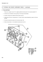
b. Disassembly/Repair — Continued
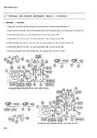
13
14
15
16
17
18
19
20
21
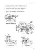
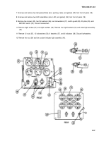
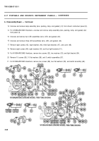
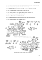
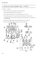
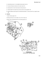
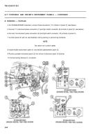
Unscrew and remove lamp assembly (lens, packing, lamp, and gasket) (41) from driver’s instrument panel (3).
For M109A4/M109A5 Howitzers, unscrew and remove lamp assembly (lens,
from panel (3).
Unscrew and remove two LED assemblies (lens, LED, and gasket) (43).
Unscrew and remove three LED assemblies (lens, LED, and gasket) (44).
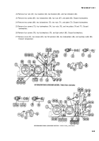
Remove eight screws (45), eight washers (46), three light brackets (47), and
Remove eight screws (49), eight washers (50), and four light brackets (51 ).
packing, lamp, and gasket) (42)
cover (48).
For M109A4/M109A5 Howitzers, remove two screws (52), two washers (53), and light bracket (54).
Remove 10 screws (55), 10 flat washers (56), and 5 switch assemblies (57).
For M109A4/M109A5 Howitzers, remove two screws (58), two flat washers (59), and switch assembly (60).
8-38
Back to Top

