TM-9-2350-311-20-1 - Page 784 of 1275
TM 9-2350-311-20-1
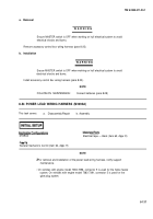
a. Disassembly/Repair
Ensure MASTER switch is OFF when working on hull electrical system to avoid
electrical shocks and bums.
Disassemble wiring harness (para 2-13).
b. Assembly
Ensure MASTER switch is OFF when working on hull electrical system to avoid
electrical shocks and bums.
Assemble wiring harness (para 2-13).
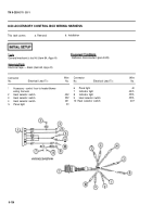
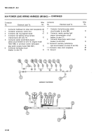
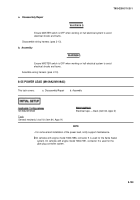
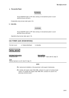
8-55 POWER LEAD (M109A2/M109A3)
This task covers:
a. Disassembly/Repair
b. Assembly
M109A2/M109A3
Tools
General mechanic’s tool kit (item 64, Appx H)
Electrical tape — black (item 62, Appx D)
NOTE
•
For removal and installation of the power lead, notify support maintenance.
Ž
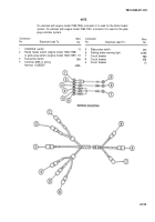
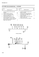
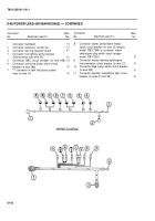
On vehicles with engine model 7083-7396, connector 5 is used for the flame heater
system. On vehicles with engine model 7083-7391, connector 5 is used for the
glow plug controller system.
8-139
WARNIN G
WARNING
Back to Top

