TM-9-2350-311-20-1 - Page 785 of 1275
TM 9-2350-311-20-1
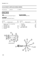
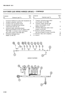
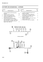
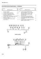
8-55 POWER LEAD (M109A2/M109A3) — CONTINUED
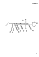
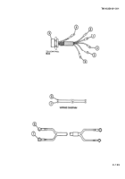
Connector
Wire
No.
Electrical Lead To:
No.
Connector
Wire
No.
Electrical Lead To:
No.
1
Connector bulkhead (to NATO slave start
receptacle)
49
2
Connector accessory control box
10
3
Connector slip ring segment board
47
4
Connector hull lighting wiring harness
(interconnects with wire 15)
10
5
Connector starter switch/flame heater
switch circuit breaker (to wire 10) (engine
model 7083-7396) or connector starter switch/
glow plug switch circuit breaker (to wire 10)
(engine model 7083-7391)
10
6
7
8
9
10
Connector fuel prime pump switch circuit
breaker (to wire 588)
10
Connector master warning Iight/engine
instrumentation circuit breaker (to wire 27)
10
Connector bilge pump switch circuit
breaker (to wire 450)
10
Connector auxiliary outlet/dome light circuit
breaker (to wires 37-38)
Connector NATO slave start receptacle
49
8-140
Back to Top

