TM-9-2350-311-20-1 - Page 986 of 1275
TM 9-2350-311-20-1
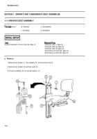
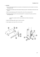
c. Assembly
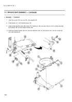
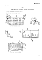
1 install horizontal adjusting bar (65), two screws (64), two flat washers (63), and two nuts (62) onto horizontal
adjusting group (56).
2 Position spring (61) between pawl (60) and backrest bracket group (52). Install headed pin (59) and new cotter
pin (58).
3 Install horizontal adjusting group (56), flat washer (55), and nut (54) at mounting stud (57).
4 Install backrest bracket group (52), reinforcement bracket (51), four washers (50), and four nuts (49) at
mounting studs (53).
NOTE
Install shims as required to provide a snug fit between cam follower and seat support
bracket.
5 Install four cam followers (48), shims (47), and four nuts (46).
6 Install adjusting lever bracket (39) and two screws’.
11-7
Back to Top


