TM-9-2350-311-20-2 - Page 109 of 828
TM 9–2350–311–20–2
2–48
2–36 BLOCKING — CONTINUED
d.
End Cleats
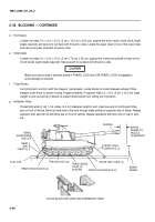
Locate one cleat 2 in. x 4 in. x 12 in. (5 cm x 10.2 cm x 30.4 cm), against the end of each chock block (eight
cleats required) and secure to car deck with 30-penny nails. Locate the upper cleat on top of the lower cleat
and secure to lower cleat with 30-penny nails.
e.
Side Cleats
Locate one cleat 2 in. x 3 in. x 10 in. (5 cm x 7.6 cm x 25 cm), against the inside and outside of each of the
chock blocks (eight cleats required). Secure each to car deck with 20-penny nails.
CAUTION
Make sure cannon tube is securely locked in TRAVEL LOCK and CAB TRAVEL LOCK is engaged to
avoid damage to howitzer.
f.
Track Blocks
Cut 34 blocks to conform with the shape of road wheels. Locate blocks on tracks between wheels. Place
wedges under block to ensure a snug fit against wheels, if required. Nail 2 in. x 4 in. (5 cm x 10.2 cm) cleat
(length to suit) across top of blocks to prevent track blocks from sliding out of position.
g.
Holddown Rods
Thread both ends of rod 1–1/4 inches (3.2 cm) diameter, length to suit. Insert one end of rod through lifting
eye on front of vehicle. Bend rod and insert other end through stake pocket on opposite side of flatcar. Repeat
operation with second rod and lifting eye on front of vehicle. Repeat operations with two rods on rear of vehi-
cle.
CHOCK BLOCK-EXPLODED AND ASSEMBLED VIEWS
FLAT CAR
REAR CHOCK BLOCK (2)
TRACK BLOCK (24)
TRACK INSIDE
CLEAT (2)
(HIDDEN)
FRONT CHOCK BLOCK (2)
BRAKE
WHEEL
BRAKE
WHEEL-TO-
MUZZLE
CLEARANCE
MUZZLE
REAR
HOLDDOWN
ROD (2)
REAR
END
CLEAT (4)
FRONT END CLEAT (4)
FRONT HOLD-
DOWN ROD (2)
Back to Top

