TM-9-2350-311-20-2 - Page 174 of 828
TM 9–2350–311–20–2
3–63
e.
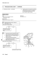
CAB HYDRAULIC SYSTEM — CONTINUED
(1)
POWER PACK HYDRAULIC PUMP MOTOR
DOES NOT OPERATE, BUT CAB LIGHTING
SYSTEM OPERATES NORMALLY.
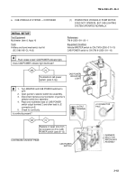
INITIAL SETUP
Test Equipment
Multimeter (item 6, Appx H)
Tools
Artillery and turret mechanic’s tool kit
(SC 5180–95–CL–A12)
References
TM 9–2350–311–20–1
Equipment Condition
Vehicle MASTER switch to ON (TM 9–2350–311–10)
CAB POWER switch to ON (TM 9–2350–311–10)
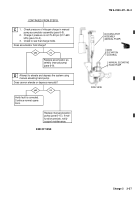
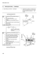
1.
Turn MASTER and CAB POWER switches to
OFF.
2.
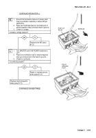
Open gunner’s selector switch box assembly.
3.
Disconnect harness at J2 connector of gunner’s
selector switch box assembly.
4.
Place one multimeter lead on CAB POWER
switch output terminal 2 and other lead to J2
connector pin E.
5.
Check for continuity.
Is continuity present?
Replace or repair wire from
J2 connector pin E to CAB
POWER switch (para 8–12).
Troubleshoot cab power
system (para 3–3g.).
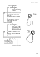
Push “press to test” CAB POWER indicator light.
Does CAB POWER indicator light illuminate?
A
yes
no
B
yes
no
CONTINUED ON NEXT PAGE
–
+
J2 CONNECTOR
PIN E
CAB POWER
INDICATOR
LIGHT
OUTPUT
TERMINAL
GUNNER’S
SELECTOR
SWITCH BOX
ASSEMBLY
CAB POWER
SWITCH
Back to Top

