TM-9-2350-311-20-2 - Page 194 of 828
TM 9–2350–311–20–2
3–82
Change 2
3–3
TROUBLESHOOTING — CONTINUED
g.
CAB POWER SYSTEM — CONTINUED
(1)
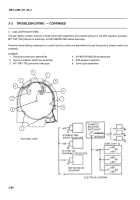
ALL CAB ELECTRICAL COMPONENTS FAIL
TO OPERATE. — CONTINUED
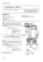
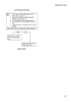
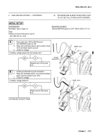
Repair electrical contact
arm assembly (para 9–3).
Verify fault is corrected.
Continue normal opera-
tions.
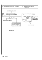
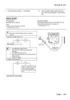
1.
Turn MASTER switch to OFF.
2.
Inspect electrical contact brushes for wear and
adjust contact arm assembly (para 9–3).
3.
Turn MASTER switch to ON.
4.
Place red multimeter lead to screw (use either of
two screws) on bottom of contact arm assembly
and black lead to ground.
5.
Check for voltage.
Is battery voltage present?
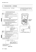
1.
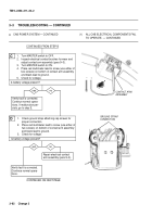
Check ground strap attaching cap screws for
proper connection.
2.
Place red multimeter lead to screw (use either of
two screws) on bottom of contact arm assembly
and black lead to ground.
3.
Check for voltage.
Is battery voltage present?
yes
no
Verify fault is corrected.
Continue normal opera-
tions. If malfunction per-
sists, go to step E.
C
yes
no
D
CONTINUED ON NEXT PAGE
CONTINUED FROM STEP B
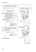
GROUND STRAP
CONNECTION
–+
CONTACT ARM
ASSEMBLY
Back to Top

