TM-9-2350-311-20-2 - Page 383 of 828
TM 9–2350–311–20–2
6–61
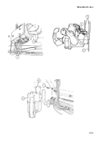
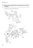
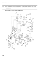
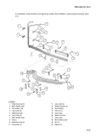
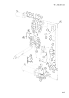
For installation, follow illustration and legend as a guide. After installation, check hydraulic fluid level (para
6–2).
1
2
1
3
4
1
3
4
6
3
5
4
3
4
3
8
7
11
3
12
9
9
10
3
12
18
17
3
12
13
3
14
16
1
15
3
12
19
20
19
20
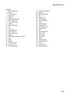
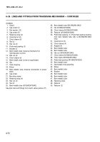
LEGEND:
1. Retaining strap (4)
2. Bent metallic tube
3. Flat washer (18)
4. Cap screw (8)
5. Retaining strap
6. Cap screw (2)
7. Bent metallic tube
8. Guard
9. Retaining strap (2)
10. Cap screw (2)
11. Cap screw (2)
12. Retaining strap (4)
13. Pipe bracket
14. Hex nut (2)
15. Cap screw
16. Retaining strap
17. Cap screw
18. Bent metallic tube
19. Nut (2)
20. Sleeve (2)
Back to Top

