TM-9-2350-311-20-2 - Page 374 of 828
TM 9–2350–311–20–2
6–52
Change 2
6–21 GUNNER’S/ASSISTANT GUNNER’S CONTROL ASSEMBLY HANDLES
This task covers:
a.
Removal
b.
Installation
INITIAL SETUP
Tools
Artillery and turret mechanic’s tool kit
(SC 5180–95–CL–A12)
Materials/Parts
Sealing compound (item 27, Appx D)
Equipment Condition
Gunner’s control assembly removed (para 6–19)
Assistant gunner’s control assembly removed (para
6–20)
NOTE
•
Some handles may have the gunner’s control lead assembly in place during removal. They are
not to be reassembled during the installation procedure.
•
Use identical service procedures for both the left and right handle assemblies.
a.
Removal
1
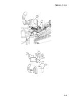
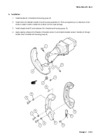
Remove shoulder screw (1) from handle (2) through access hole in bracket and housing group (3).
2
Remove setscrew (4) and straight shaft (5) from bracket and housing group (3).
3
Remove handle (2) from bracket and housing group (3).
NOTE
Retain shims unless new components are to be installed.
4
Remove shims (6) from bracket and housing group (3).
NOTE
If gunner’s control lead assembly is connected to the gunner’s control assembly handle, go to step 5.
5
Remove two cap screws (7) and two lockwashers (8).
6
Remove cap screw (9) and lockwasher (10).
7
Separate left and right handle halves (11 and 12).
8
Drive out headless straight pin (13).
9
Disconnect gunner’s control lead assembly (14) from setscrews (15).
Back to Top

