TM-9-2350-311-20-2 - Page 366 of 828
TM 9–2350–311–20–2
6–44.6
Change 2
6–17 HYDRAULIC FILTER ASSEMBLY — CONTINUED
d.
Assembly — Continued
3
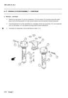
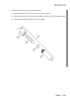
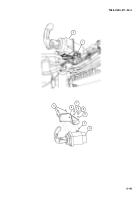
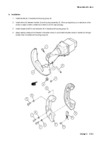
To assemble Diagnetics Corporation filter assembly (2):
(a)
Install new packing retainer (24) and new preformed packing (23) into groove on the top of filter hous-
ing (18). Ensure the cut ends of packing retainer overlap smoothly and do not protrude out of the
groove.
NOTE
Ensure spring is placed in bottom of bowl with axis parallel to bowl centerline.
(b)
Install new filter element (19) into the filter housing (18) ensuring the hole of the filter element is visible.
(c)
Screw filter housing (18) into manifold (13) until firmly seated.
e.
Installation
1
If mounting bracket (14) was removed, position mounting bracket on cab ceiling. Install and hand tighten
four flat washers (17), four new lockwashers (16), and four cap screws (15).
2
If necessary for replacement, install identification marker (17.1) (para 2–7).
3
Mount two filter assemblies (2) to mounting bracket (14) using four new lockwashers (12) and four cap
screws (11).
23
24
13
19
18
2
SPRING
18
24
23
Back to Top

