TM-9-2350-311-20-2 - Page 368 of 828
TM 9–2350–311–20–2
6–46
Change 2
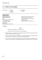
6–18 HYGROSCOPIC BREATHER AND AIR LINE FILTER
This task covers:
a.
Removal
b.
Installation
c.
Service
INITIAL SETUP
Applicable Configuration
M109A4/M109A5 howitzers
Tools
Artillery and turret mechanic’s tool kit
(SC 5180–95–CL–A12)
Utility pail (item 7, Appx H)
Materials/Parts
Caps and plugs (item 7, Appx D)
Dessicant (item 11.1, Appx D)
Locknut (item 97, Appx G)
Lockwashers (2) (item 80, Appx G)
Preformed packing (item 45, Appx G)
Wiping rag (item 25, Appx D)
Equipment Condition
Discharge hydraulic pressure (para 6–3)
a.
Removal
NOTE
•
There are two possible hygroscopic breather configurations. Both, however are removed and
installed the same way.
•
Dispose of hydraulic fluid in accordance with local regulations.
•
All hydraulic lines and parts must be capped to prevent contaminants from entering the hydrau-
lic system and causing internal damage to hydraulic components.
1
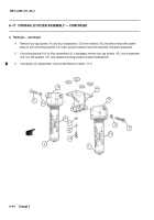
Disconnect adapter (1) with attaching tube (2) from air line filter (3).
2
Disconnect air line filter (3) and nipple (4) from fitting (5).
3
Unscrew and remove hygroscopic breather (6), or hygroscopic breather (6.1), fitting (5), locknut (7), and
preformed packing (8) from mounting bracket (9). Discard preformed packing and locknut.
4
If mounting bracket (9) is damaged, remove two machine bolts (10), two lockwashers (11), and mounting
bracket for replacement. Discard lockwashers.
b.
Installation
1
If mounting bracket (9) was removed, secure to cab wall using two new lockwashers (11) and two machine
bolts (10).
2
Secure fitting (5) on mounting bracket (9) using new locknut (7).
CAUTION
If new air line filter is being installed, remove foam from inside or hydraulic fluid will collect in air line
filter causing damage to equipment.
Back to Top

