TM-9-2350-311-20-2 - Page 370 of 828
TM 9–2350–311–20–2
6–48
Change 2
6–19 GUNNER’S CONTROL ASSEMBLY
This task covers:
a.
Removal
b.
Installation
INITIAL SETUP
Tools
Artillery and turret mechanic’s tool kit
(SC 5180–95–CL–A12)
Materials/Parts
Caps and plugs (item 7, Appx D)
Lockwashers (2) (item 65 Appx G)
Self-locking nut (item 98, Appx G)
Equipment Condition
CAB POWER switch to OFF (TM 9–2350–311–10)
Discharge hydraulic pressure (para 6–3)
CAUTION
All hydraulic lines and ports must be capped to prevent contaminants from entering the hydraulic
system and causing internal damage to hydraulic components.
NOTE
Dispose of hydraulic fluid in accordance with local regulations.
a.
Removal
1
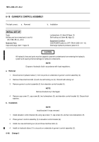
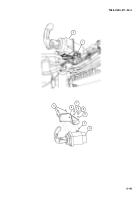
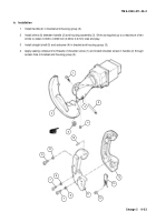
Disconnect six hydraulic tubes (1) from six ports on underside of gunner’s control assembly (2).
2
Remove three machine bolts (3) and one self-locking nut (4). Discard self-locking nut.
3
Remove gunner’s control assembly (5) from elevation control bracket (6).
NOTE
Remove bracket only if damaged.
4
Remove cap screw (7), cap screw (8), two lockwashers (9), and elevation control bracket (6). Discard lock-
washers.
b.
Installation
NOTE
Install bracket if it was removed.
1
Install elevation control bracket (6) using cap screw (7), cap screw (8), and two new lockwashers (9).
2
Place gunner’s control assembly (5) in elevation control bracket (6).
3
Install one new self-locking nut (4) and three machine bolts (3).
4
Install six hydraulic tubes (1) to six ports on underside of gunner’s control assembly (2).
Back to Top

