TM-9-2350-311-20-2 - Page 397 of 828
TM 9–2350–311–20–2
6–75
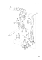
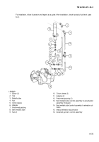
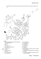
For installation, follow illustration and legend as a guide. After installation, check hydraulic fluid level (para
6–2).
1
1
3
2
13
9
10
11
9
10
11
12
4
14
8
5
6
7
15
16
LEGEND:
1. Elbow (2)
2. Tee
3. Metallic tube
4. Nut
5. Clinch sleeve
6. Adapter
7. Preformed packing
8. Bent metallic tube
9. Nut (2)
10. Clinch sleeve (2)
11. Adapter (2)
12. Preformed packing (2)
13. Bent metallic tube (control assembly to accumulator
assembly (manual))
14. Bent metallic tube (control assembly to elevation cyl-
inder)
15. Manual elevation accumulator
16. Assistant gunner’s control assembly
Back to Top


