TM-9-2350-311-20-2 - Page 751 of 828
TM 9--2350--311--20--2
Change 4
B--3
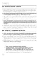
d. Column 4, Maintenance Level. Column 4 specifies each level of maintenance authorized to perform each function
listed in Column 3, by indicating work-time required each expressed as man-hours in whole hours or decimals in the
appropriate subcolumn. This work-time figure represents the active time required to perform that maintenance func-
tion at the indicated level of maintenance. If the number or complexity of the tasks within the listed maintenance func-
tion vary at different maintenance levels, appropriate work-time figures are to be shown for each level. The work-time
figure represents the average time required to restore an item (assembly, subassembly, component, module, end
item,orsystem)toaserviceableconditionundertypicalfield operatingconditions. This timeincludes preparationtime
(includinganynecessarydisassembly/assemblytime),troubleshooting/faultlocationtime,andqualityassurancetime
in addition to the time required to perform the specific tasks identified for the maintenance functions authorized in the
maintenance allocation chart. The symbol designations for the various maintenance levels are as follows:
Field:
C
Operator or crew maintenance
.........
O
Unit maintenance
.........
F
Direct support maintenance
.........
Sustainment:
L
Specialized Repair Activity (SRA)
5
.........
H
General support maintenance
.........
D
Depot maintenance (**indicates
.........
time at depot maintenance)
e. Column 5, Tools and Test Equipment reference code. Column 5 specifies, by code, those common tool sets (not indi-
vidualtools),commonTMDE,andspecialtools,specialTMDE,andspecialsupportequipmentrequiredtoperformthe
designated function. Codes are keyed to tools and test equipment in Section III.
f.
Column 6, Remarks. When applicable, this column contains a letter code, in alphabetical order, which is keyed to the
remarks contained in Section IV.
B--4
EXPLANATION OF COLUMNS IN TOOL AND TEST EQUIPMENT REQUIREMENTS,
SECTION III.
a. Column 1, Reference Code. The tool and test equipment reference code correlates with a code used in the MAC,
Section II, Column 5.
b. Column 2, Maintenance Level. The lowest level of maintenance authorized to use the tool or test equipment.
c.
Column 3, Nomenclature. Name or identification of the tool or test equipment.
d. Column 4, National Stock Number. The National Stock Number of the tool or test equipment.
e. Column 5, Tool Number. The manufacturer’s part number, model number, or type number.
B--5
EXPLANATION OF COLUMNS IN REMARKS, SECTION IV.
a. Column 1, Remarks Code. The code recorded in column 6, Section II.
b. Column2,Remarks. Thiscolumnlistsinformationpertinenttothemaintenancefunctionbeingperformedasindicated
in the MAC, Section II.
5
This maintenance level is not included in Section II, column (4) of the Maintenance Allocation
Chart. Functions to this level of maintenance are identified by a work-time figure in the “H” col-
umn of Section II, column (4), and an associated reference code is used in the Remarks column
(6). This code is keyed to Section IV, Remarks, and the SRA complete repair application is ex-
plained there.
Back to Top


