TM-9-2350-311-34-1 - Page 174 of 352
INITIAL SETUP
Equipment Conditions
Tools
Materials/Parts
References
33A
TM 9-2350-311-34-1
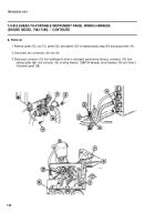
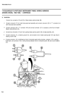
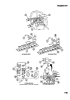
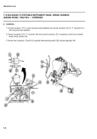
7-10 BULKHEAD-TO-PORTABLE INSTRUMENT PANEL
WIRING HARNESS
(ENGINE MODEL 7083-7391)
This task covers:
a. Removal
b. Disassembly
c. Assembly
d. Installation
General mechanic’s tool kit (item 14, Appx C)
Batteries disconnected (TM 9-2350-311-20-1)
Portable instrument panel removed (TM 9-2350-311-20-1)
Electrical tape — black (item 25, Appx B)
TM 9-2350-311-20-1
Connector
Wire
No.
Electrical Lead To:
No.
1
2
3
4
5
6
7
8
9
10
11
12
13
14
15
Aeration detector
Aeration detector
Master switch
Engine oil pressure gage
Engine water temperature gage
Transmission oil temperature gage
Transmission oil pressure gage
Warning lamp switch
Panel lights
Fuel level gage and switch
Engine instrument and master warning light
Master switch
Master switch
Ground
Parking brake warning switch and light
352B
352A
459B
36
324
321
509
40
29-31
27
459A
459
GND
509E
Connector
Wire
No.
Electrical Lead To:
No.
16
17
18
19
20
21
22
23
24
25
26
27
28
29
Parking brake warning light
509E
In-tank fuel pump and generator system relay 76B
Starter switch — neutral safety switch
14
Glow plug switch
486A
Connector to 415 air cleaner blower
motor relay
27B
Accessory control box
400
Glow plug lamp lead
486
Not used
415
Not used
588
Not used
588L
Not used
588-588L
Voltage regulator
400-459B
Bulkhead connector
Portable instrument connector
7-38
Back to Top


