TM-9-2350-311-34-1 - Page 292 of 352
TM 9-2350-311-34-1
10-2 COOLANT HEATER — CONTINUED
a. Assembly — Continued
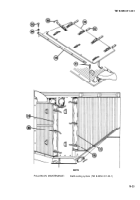
15 Install fuel tube (40) and resistor (55) as an assembly.
16 Install cable (62) to resistor (55) with two new assembled screws (60) and two nuts (61).
17 Install tapping plate (59).
18 Install two screws (57) to tapping plate (59).
19 Install igniter (53) and new gasket (56).
20 Install preheat resistor (55) to igniter (53) with two nuts (54).
21 Install lead (51) to igniter (53) with new assembled screw (50) and new Iockwasher (52).
22 Install end plate (49) and four nuts (48).
23 Install new preformed packing (47), flat washer (46), connector (34), and overheat thermostat (20).
24 Install retainer (45), new Iockwasher (44), and nut (43).
25 Install lead (42) to overheat thermostat (20).
26 Install bracket (39) and two screws (41).
27 Install fuel control valve (38) and two screws (37) to bracket (39) and fuel tube (40).
28 Tighten nut (36).
29 Install lead (35) to terminal strip (8).
30 Install two leads (32 and 33) to connector (34) on overheat thermostat (20).
31 Install nut (30) and new compression sleeve (31).
32 Install flame detector switch (23) and tighten nut (30).
10-32
Back to Top


