TM-9-2350-311-34-2 - Page 151 of 552
TM 9-2350-311-34-2
3
4
5
6
7
8
9
10
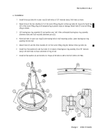
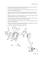
Install plate spacer (36), shims or plate spacers (35), new self-locking nut (34), and cap screw (33) inside
cab on top of trunnion bracket assembly (20) at center top screw hole.
Install shims or plate spacers (40), six flat washers (39), six new self-locking nuts (38), and six cap screws
(37) on top of trunnion bracket assembly (20).
Install shims (32), three flat washers (31), three new self-locking nuts (30), cap screw (29), and two cap
screws (28) on top left side of trunnion bracket assembly (20). Cap screw (29) is longer than cap screws
(28).
Install five flat washers (27), five new self-locking nuts (26), and five cap screws (25) in right side of trunnion
bracket assembly (20). Cap screws are 3.25 inches (8.3 cm) long.
Install shims (24), five flat washers (23), five new self-locking nuts (22), and five cap screws (21) in left side
of trunnion bracket assembly (20). Cap screws are 2.75 inches (7.0 cm) long.
Remove turret lifting sling (41) and gun tube sling (12) from trunnion bracket (20) and attach gun tube sling
and hoist (13) to muzzle brake (14).
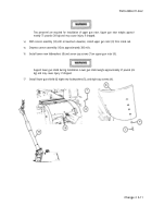
Elevate cannon assembly (10) to maximum elevation and install three new self-locking bolts (19) in bottom
of trunnion bracket assembly (20). Torque bolts to 270 lb-ft (366 N ·m).
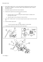
Install assistant gunner ’s control assembly (TM 9-2350-311-20-2).
Change 2 5-9
Back to Top

