TM-9-2350-311-34-2 - Page 413 of 552
TM 9--2350--311--34--2
Change 3
9--19
20
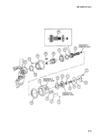
Remove six self-locking screws (26) from inside housing, and remove mechanical housing (16) and gasket
(27) from traversing mechanism (28). Discard gasket and self-locking screws.
21
Remove four cap screws (29) and shaft coupling half (30) from shaft adapter (31).
22
Place clutch and shaft assembly in vise. Remove sleeve bearing (32).
23
Bend locking tabs on key washer (33) to disengage key washer from round nut (34).
24
Remove round nut (34) and key washer (33). Discard key washer.
25
Pull clutch shaft (35) and sleeve bearing (36) from shaft adapter (31) and mechanical housing (16). Remove
woodruff key (37) from clutch shaft.
NOTE
Do not remove inner bearing ring or roller bearing unless damaged and repair is necessary.
26
Remove shaft adapter (31) from inner bearing ring (38) and roller bearing (39) by forcing shaft adapter out
of mechanical housing (16).
27
Remove two plugs (40) and two preformed packings (41). Discard preformed packings.
28
Push three valve pistons (42) and three packing assemblies (43) out of mechanical housing (16). Discard
packing assemblies.
29
Remove retaining ring (44) to release seal (45). Discard retaining rings and seal.
30
Remove four plugs (16.1) and four preformed packings (16.2) from mechanical housing (16). Discard
preformed packing.
b. Inspection
For proper cleaning and inspection procedures for ball bearing (12) and sleeve bearings (32 and 36), refer
to TM 9--214.
16.1
16.2
Back to Top


