TM-9-2350-311-34-2 - Page 418 of 552
TM 9-2350-311-34-2
9-5
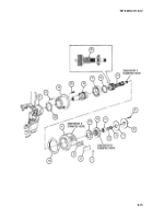
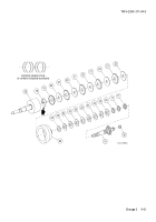
OIL PUMP AND LINES
This task covers:
a. Removal
b. Disassembly
c. Inspection
d. Assembly
e. Installation
INITIAL SETUP
Tools
Artillery and turret mechanic’s tool kit
(SC 5180-95-CL-A12)
Artillery field maintenance tool kit
(SC 4933-95-CL-A06)
Drain pan (item 12, Appx F)
Materials/Parts
Hydraulic oil pump parts kit (item 116, Appx E)
Lo&washers (4) (item 82, Appx E)
Lubricating oil (4 quarts) (item 25, Appx B)
Equipment Condition
Discharge hydraulic pressure (TM 9-2350-311-20-2)
Traversing mechanism cover plate removed
(TM 9-2350-311-20-2)
a. Removal
Wear safety glasses and steel-tipped shoes to avoid possible injury while handling equipment.
1
Remove plug (1).
2
Place drain pan of at least two-gallon capacity below drain plug (2) at bottom center of traversing mecha-
nism lower housing (3). Remove drain plug and drain lubricant. Install drain plug and tighten.
3
Disconnect outlet tube (4) by loosening compression hex nuts of adapter (5) and elbow (6).
4
Remove adapter (5) from traversing mechanism upper housing (7).
5
Remove elbow (6) from oil pump (8).
6
Disconnect inlet tube (9) and sleeve (10) by loosening two compression hex nuts (11) of elbow assembly
(12) and elbow (13).
7
Remove elbow (13) from oil pump (8).
8
Remove cap (14) and remove elbow assembly (12) from traversing mechanism lower housing (3).
9-24
Change 2
Back to Top


