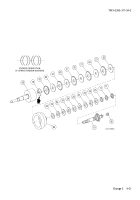
TM-9-2350-311-34-2 - Page 423 of 552
TM 9-2350-311-34-2
d. Assembly
1
Place retaining plate (19) in a soft-jawed vise.
2
Install new outlet valve seat (38), new outlet valve plate (37), new helical compression spring (36), new ring
spacer (35), and new upper plug (34) in retaining plate (19).
3
Install new helical compression spring (33), new inlet valve seat (32), new inlet valve pump seat (31), new
externally threaded ring (30), new ring spacer (29), and new lower plug (28) in retaining plate (19).
4
Place new helical compression spring (27) on oil pump body (18). Insert stem assembly (25) through helical
compression spring and oil pump body, alining pin (39) of stem assembly with slot in oil pump body.
5
Apply force to stem assembly (25) to compress helical compression spring (27) and thread plunger (26)
onto stem of stem assembly. Turn plunger until it is completely seated on shoulder of stem assembly.
Lightly peen stem assembly thread in one place to lock plunger to stem.
6
Install two flat washers (24), roller (23), and headless grooved pin (22) in clevis of stem assembly (25). Se-
cure headless grooved pin with two new retaining rings (21).
7
Place a new gasket (20) between oil pump body (18) and retaining plate (19).
9-29
Back to Top


