TM-9-2350-311-34-2 - Page 432 of 552
TM 9-2350-311-34-2
11-1 M15 QUADRANT MOUNTING BRACKET
This task covers:
a. Removal
b. Installation
INITIAL SETUP
Tools
Artillery and turret mechanic’s tool kit
(SC 5180-95-CL-A12)
Artillery field maintenance tool kit
(SC 4933-95-CL-A06)
Level, cross test (item 8, Appx F)
Quadrant, M1A1 gunner’s (item 14.1, Appx F)
Materials/Parts
Lockwashers (4) (item 86, Appx E)
Pin assemblies (2) (item 157, Appx E)
Equipment Condition
M15 elevation quadrant removed
(TM 9-2350-311-20-2)
a. Removal
1
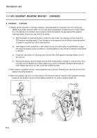
Remove four cap screws (1) and four lockwashers (2) from M15 quadrant mounting bracket (3). Discard
lockwashers.
2
Loosen nuts on two pin assemblies (4). Tap two pin assemblies in with brass hammer. Remove M15 quad-
rant mounting bracket (3) with two pin assemblies.
3
Remove two pin assemblies (4), headless straight pin (5) and quadrant ring (6) from M15 quadrant mount-
ing bracket (3). Discard pin assemblies.
b. Installation
1
Make certain that all mating surfaces of M15 quadrant mounting bracket (3), cannon trunnion (7) and bear-
ing retaining plate (8) are free of dirt, grease, and burrs.
2
Install M15 quadrant mounting bracket (3), four new lockwashers (2) and four cap screws (1). Hand tighten
four cap screws only; do not tighten to final torque.
3
Install quadrant ring (6) on M15 quadrant mounting bracket (3) alining reference marks on quadrant ring
with reference marks on M15 quadrant mounting bracket.
11-2
Change 2
Back to Top


