TM-9-2350-311-34-2 - Page 434 of 552
TM 9-2350-311-34-2
11-1 M15 QUADRANT MOUNTING BRACKET - CONTINUED
b.
Installation - Continued
4
5
6
7
8
9
10
11
12
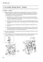
Install cross test level (9) on M15 quadrant mounting bracket (3) using the four 1/2-20 x 1-3/4 cap screws
(10) and flat washers (11) supplied with cross test level. Torque four cap screws to 20 Ib-ft (27 N·m).
Place M1A1 gunner’s quadrant (12), (end-for-end correction applied, and breech ring error applied) on
breech quadrant seat (13). The M1A1 gunner’s quadrant should read 0 elevation ± 0.5 mils. If M1A1 gun-
ner’s quadrant does not indicate this value, elevate or depress cannon assembly until M1A1 gunner’s quad-
rant does indicate 0 elevation ± 0.5 mils.
Move M15 quadrant mounting bracket (3) as required until bubble in elevation level vial (14) of cross test
level (9) is centered. Only a slight amount of movement of M15 quadrant mounting bracket should be re-
quired. When bubble in cross test level elevation level vial is centered, torque two accessible cap screws (1)
which secure M15 quadrant mounting bracket to cannon trunnion (7) to 30 Ib-ft (41 N·m).
Remove cross test level (9) from M15 quadrant mounting bracket (3). Tighten remaining two cap screws (1)
to 30 Ib-ft (41 N·m).
Repeat steps 4 through 7.
Drill and ream, as required, the two holes in the M15 quadrant mounting bracket (3) and cannon trunnion (7)
for two new pin assemblies (4).
Install two new pin assemblies (4). Torque nuts on pin assemblies to 9 Ib-ft (12 N·m).
Install cross test level (9) on M15 quadrant mounting bracket (3) and torque mounting cap screws (10) to 20
Ib-ft (27 N·m).
Place M1A1 gunner’s quadrant (12) on cant seats of breechblock. Level vial bubble (15) must be approxi-
mately centered. Remove M1A1 gunner’s quadrant. Bubble in cross-level vial (16) of cross test level (9)
must be approximately centered. Mark exact position of bubble ends with a felt-tipped marker or grease
pencil.
11-4
Back to Top


