TM-9-2350-311-34-2 - Page 436 of 552
TM 9-2350-311-34-2
11-1 M15 QUADRANT MOUNTING BRACKET - CONTINUED
b. Installation - Continued
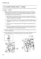
13 Elevate cannon assembly to maximum elevation, observing bubble in cross-level vial (16) continuously.
Bubble must remain stationary within 1/2 of a cross-level vial graduation. If bubble does not remain station-
ary, note the amount of deviation, then proceed to realine the quadrant ring (6) between M15 quadrant
mounting bracket (3) and cross test level (9) as follows:
(a)
(b)
(c)
(d)
With the weapon at maximum elevation, loosen four cap screws (10) securing cross test level (9) to
M15 quadrant mounting bracket (3) just enough to loosen quadrant ring (6) without disturbing position
of bubble in cross-level vial (16) of cross test level.
Insert blade of a thin screwdriver or other similar tool into one of the holes on circumference of quad-
rant ring (6) and adjust position clockwise or counterclockwise so that one-half of deviation noted above
is removed.
Torque four cap screws (10) securing cross test level (9) to M15 quadrant mounting bracket (3) to 20
Ib-ft (27 N·m).
Depress and elevate cannon through full travel while noting position of bubble in cross-level vial (16) of
cross test level (9). Bubble must remain stationary as cannon is elevated and depressed through full
travel. Repeat step 13 (a), (b), and (c) until this condition prevails.
14 Mark location of quadrant ring (6) or secure quadrant ring in position. Remove cross test level (9) from M15
quadrant mounting bracket (3).
15 Make sure quadrant ring (6) is in correct position. Drill and ream holes as required in M15 quadrant mounting
bracket (3) and quadrant ring for locating headless straight pin (5). Install a headless straight pin.
11-6
Back to Top


