TM-9-2350-311-34-2 - Page 485 of 552
TM 9-2350-311-34-2
4
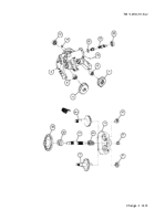
Carefully lower housing assembly (5) over hydraulic drive unit (4) while guiding cylinder block (14) along an-
gle of housing assembly. When housing assembly reaches seal and bearing retainer sleeve (3) make sure
it is squarely over seal and bearing retainer assembly to avoid misalining and jamming parts inside.
5
Install 12 cap screws (2) and torque to 12 in-lb (1.4 N.m).
6
Secure 12 cap screws (2) with new lockwire (1).
7
If necessary for replacement, install identification plate (10), instruction plate (9), and six drive screws (8).
8
If necessary for replacement, install instruction plate (12) and two tapping screws (11).
Change 2 14-25
Back to Top


