TM-9-2350-311-34-2 - Page 484 of 552
TM 9-2350-311-34-2
14-5 HYDRAULIC MOTOR
This task covers:
a. Disassembly
b. Inspection
c. Assembly
INITIAL
SETUP
Tools
Artillery and turret mechanic ’s tool kit
(SC 5180-95-CL-A12)
Materials/Parts
Lockwire (item 35, Appx E)
Motor seal replacement parts kit (item 147, Appx E)
Equipment Condition
Hydraulic motor with safety relief valve assembly
removed (para 9-1 )
Safety relief valve assembly removed from hydraulic
motor (para 14-6)
a. Disassembly
1
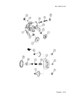
Remove lockwire (1) and 12 cap screws (2) from seal and bearing retainer sleeve (3). Discard lockwire.
Do not allow the bearings of the hydraulic drive unit to become misalined or jammed in seal and
bearing retainer sleeve.
NOTE
When removing seal and bearing retainer sleeve, use care to prevent the parts of the hydraulic drive
unit from separating.
2
Remove seal and bearing retainer sleeve (3) and hydraulic drive unit (4) from housing assembly (5).
3
Remove seal (6) and preformed packing (7) from seal and bearing retainer sleeve (3). Discard seal and pre-
formed packing.
4
If necessary for replacement, remove six drive screws (8), instruction plate (9), and identification plate (10).
5
If necessary for replacement, remove two tapping screws (11) and instruction plate (12).
b. Inspection
1
Inspect seal and bearing retainer sleeve (3). If cracked or broken, replace hydraulic motor (13).
2
Inspect housing assembly (5). If cracked or broken, replace hydraulic motor (13).
c. Assembly
1
Install new preformed packing (7) into groove around outside of seal and bearing retainer sleeve (3).
2
Install new seal (6) on seal and bearing retainer sleeve (3).
3
Install seal and bearing retainer sleeve (3) over bearings on hydraulic drive unit (4).
14-24 Change 2
Back to Top


