TM-9-2350-358-BD - Page 163 of 343
TM 9-2350-358-BD
7-3.
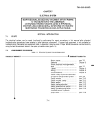
REPAIR PROCEDURE INDEX
PARA
Motor, starter, Inoperative .
......................................................................................................................................
7-5
Starter switch, Inoperative .
......................................................................................................................................
7-6
Brush, electrical, motor generator, worn .
................................................................................................................
7-7
Switch, relay, oil pressure activated, air cleaner and generator system, inoperative .
.............................................
7-9
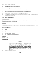
Switch, master, Inoperative .
....................................................................................................................................
7-10
Switch, neutral, safety, Inoperative .
.........................................................................................................................
7-11
Relay, master, inoperative.
......................................................................................................................................
7-12
Relay, starter protection, inoperative .
......................................................................................................................
7-13
Relay, generator/fuel pumps, inoperative .
...............................................................................................................
7-14
Relay, hydraulic pump motor, inoperative .
..............................................................................................................
7-15
Overload sensor, hydraulic pump motor, inoperative.
.............................................................................................
7-16
8.
Record BDAR action taken.
When mission is complete, as soon as practical, repair the equipment/system using
standard maintenance procedures.
SECTION II.
ELECTRICAL GENERATION AND STORAGE SYSTEM
7-4.
GENERAL
The electrical system on the M109A6 is a 24-volt negative ground, direct current system.
Electrical current storage for
starting and standby circuits is provided by batteries.
The batteries are connected in a series-parallel configuration to
provide 24 V dc current.
All electrical power to circuits can be turned off by the MASTER power switch.
The MASTER
power switch prevents accidental discharge of the batteries if a subsystem is not turned off.
7-3
Back to Top


