TM-9-2520-215-34 - Page 30 of 508
TM 9--2520--215--34
0005 00--2
THEORY OF OPERATION -- CONTINUED
0005 00
HYDRAULIC SYSTEM – Continued
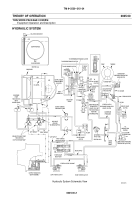
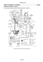
Action of Hydraulic System in Neutral Converter Drive, No Steer
NOTE
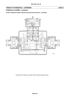
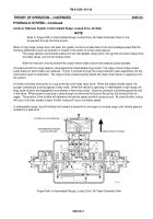
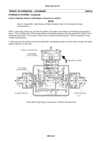
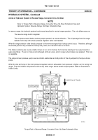
Refer to Torque Path in Neutral Converter Drive, No Steer Schematic View for the torque path
through the transmission.
Normal oil flow lubricating the pump drive gear train accumulates in the lower cavities of the torque converter housing
when the engine is running and the input scavenge pump and oil pressure are in operation. The two--section scav-
enge pump picks up the oil (along with air) and pumps it to the output reduction gear where it lubricates the brakes
and gearing. The same oil and air then return to the transmission at the output gear compartment.
Oil from the sump lubricates the brakes coolant pump, output--driven pressure pump, and the input--driven pressure
pump. Only the input--driven pressure pump and scavenge pump are rotating while the vehicle is not moving, so only
the input--pressure pump is supplying pressure.
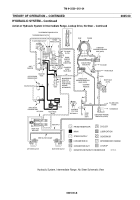
Oil pumped by the input--driven pump flows through a pair of filters to the main pressure regulator valve and to the
range selector valve. There is a relief valve parallel to the filters, which opens only if the filters are clogged.
The main pressure regulator valve moves down to a position in which oil pressure into the regulator balances the
spring pressure pushing upwards on the valve. A passage connecting the range selector valve at the top of the main
pressure regulator valve supplies additional main pressure to act upon the valve and push it downward. This result in
a lower main pressure in neutral (and intermediate and high ranges). In neutral, main pressure is blocked at the
range selector valve except for the passage to the top of the main pressure regulator valve mentioned above.
Excess oil from the main pressure regulator valves flow to the steer clutch pressure regulator valve and to the steer
valves. The steer clutch pressure regulator valve moves to the right and permits oil flow to the torque converter and,
when pump volume is sufficient, through bypass ports to the lubrication system. In the no steer position, no oil passes
through the steer valves.
Oil to the torque converter branches off to the right and actuates the converter pressure regulator valve. This valve
regulates the oil flow to the converter at 80 psi. Any excess oil bypasses the converter and is directed by the convert-
er pressure regulator valve to the oil cooler. The remainder of the oil flows through the converter and then to the cool-
er circuit. A relief valve parallels the cooler circuit but opens only if the cooler is clogged or cannot handle the volume
of flow directed to it.
From the cooler, oil passes through a pair of filters and to the lubrication regulator valve. A relief valve parallels this
line but opens only if the filter is clogged. Excess oil beyond that required to maintain lubrication pressure returns to
transmission reservoir.
In addition to supplying lubricating oil to the steer clutch lubrication valve and other points in the transmission, the lu-
brication circuit supplies the governor with oil. The pilot type (or fluid velocity type) governor produces a pressure
which is proportional to the speed of a rotating, oil filled ring. This pressure actuates the shift inhibitor and lockup
relay valve. However, in neutral operation, these components have no function.
Back to Top


