TM-9-2520-215-34 - Page 35 of 508
TM 9--2520--215--34
0005 00--7
THEORY OF OPERATION -- CONTINUED
0005 00
HYDRAULIC SYSTEM – Continued
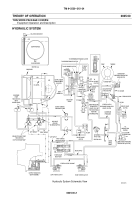
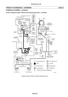
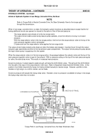
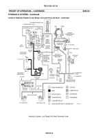
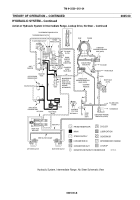
Action of Hydraulic System in Intermediate Range, Lockup Drive, No Steer
NOTE
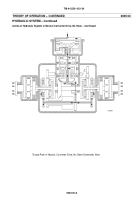
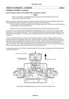
Refer to Torque Path in Intermediate Range, Lockup Drive, No Steer Schematic View for the
torque path through the transmission.
When in high range, lockup drive, left steer, the system functions as described in this work package except that the
following additional circuits are opened (or closed) to the action of oil flow and pressure:
The range selector valve directs pressure to the intermediate range clutch, through the converter lockup timer
and relay valves, and into the lockup clutch.
When the vehicle is moving forward the output--driven brake coolant and pressure pump operates.
Oil pressure from the range selector valve applies the intermediate range clutch. The output--driven brake coolant
pump draws air when brakes are released. The air is pumped through the output reduction gear assemblies into the
transmission gear compartment. The output--driven pressure pump assists the input--driven pump in supplying oil to
the system.
A throttle controlled lever pivots on a lug at the top of the relay valve cover. When the engine throttle opens, the
plunger compresses a spring against a relay valve. When the vehicle is operating in intermediate or high range, the
relay valve controls the engagement and release of the lockup clutch. Governor pressure is exerted against the end
of the valve. When governor pressure is great enough to overcome the force of the spring, the lockup clutch en-
gages. The position of the throttle will determine the vehicle speed at which lockup occurs. At closed throttle, lockup
will occur at a lower speed; at open throttle, lockup will occur at a higher speed.
In intermediate range, the shift inhibitor will prevent a downshift to low range (or reverse range) until vehicle speed is
reduced to a safe level.
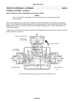
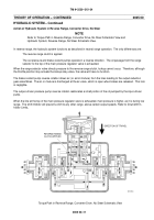
Torque Path in Intermediate Range, Lockup Drive, No Steer Schematic View
LOCKUP CLUTCH APPLIED
INTERMEDIATE RANGE
CLUTCH APPLIED
DIRECTION OF TRAVEL
07i212m
Back to Top


