TM-9-2520-215-34 - Page 41 of 508
TM 9--2520--215--34
0005 00--13
THEORY OF OPERATION -- CONTINUED
0005 00
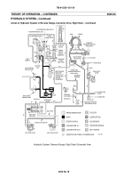
HYDRAULIC SYSTEM – Continued
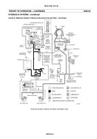
Action of Hydraulic System in Neutral, Converter Drive, Right Steer
NOTE
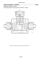
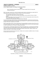
Refer to Torque Path in Reverse Range, Converter Drive, Right Steer Schematic View for
torque path through the transmission.
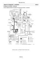
The description for neutral range operation applies to this paragraph. The only differences are that pressure is not
blocked at the steer control valve, and the lubrication pressure is not blocked at the right steer clutch.
At the steer control valve, the right (lower) valve moves to the right, while the left (upper) valve moves to the left. The
movement of the left valve to the left has no effect. Steer pressure remains blocked at that point. However, the move-
ment of the right valve to the right allows pressure to be directed to the right steer clutch. When pressure enters the
central area of the steer valve, it flows to the area at the right end of the valve. This pressure opposes rightward
movement, regulating the pressure flowing to the right steer clutch. Thus a limited rightward movement of the steer
control will result in a limited steer apply pressure. Further movement will increase the applied pressure.
Partial to full steer is available. The degree of steer is proportional to the movement of the vehicle steer control. In
partial steer, the steer clutch is slipping but operating. In full steer, clutch is completely applied and there is no slip-
page.
When the right steer clutch is applied, the right steer clutch lubrication valve opens. This permits lubricating oil to flow
over steer clutch plates.
Torque Path in Reverse Range, Converter Drive, Right Steer Schematic View
FASTER ROTATION
LEFT STEER
CLUTCH APPLIED
REVERSE RANGE
CLUTCH APPLIED
DIRECTION OF TRAVEL
SLOWER ROTATION
07i218m
Back to Top

