TM-9-2520-234-35 - Page 39 of 323
PAR 8-9
CHAPTER 2
DESCRIPTION AND OPERATION
Section I. DESCRIPTION AND OPERATION OF INPUT TRANSFER ASSEMBLY
8.
INPUT TRANSFER GEARING
a. Input Transfer Gearing
—
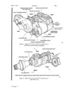
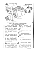
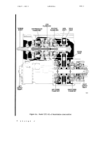
Components (fig. 373, fold-out 2)
(1) A cast aluminum transfe r
housing 126 encloses and supports the
transfer gearing. A cast aluminum flange
adapter 19 connects the vehicle engine
flywheel housing to the transfer gear hous-
ing. The rear of transfer housing 126 is
bolted to the torque converter housing.
(2) A spline d
engine coupling
shaft 23 delivers engine torque to the gear
train. The gear train consists of a 68-tooth
drive gear 25, a 52-tooth idler cluster gear
34, a 34- and 54-tooth cluster gear 41, and
a 66-tooth converter pump cover drive
gear 67. These gears have 6-pitch teeth.
The drive gear is supported in housing 126
and adapter 19 by single-row ball bearings
24 and 27. Idler gear 34 is supported on a
spindle 5 by a double-row ball bearing 35.
Idler cluster gear 41 is supported o n
spindle 153 by two straight roller bearings
38 and 40. Converter pumpcover drive
gear 67 is bolted to converter cove r
assembly 68.
Idler gear 34 includes a
36-tooth oil pump drive gear .
The
29-tooth oil pump driven gear 109 i s
supported by a single-row ball bearing 110.
b.
to the
splined
Operation of Input Transfer
Gearing (fig. 20)
(1) Engine rotation is transmitted
68-tooth transfer drive gear by a
coupling shaft.
The drive gear
drives the 52-tooth gear which, in turn,
meshes with the 34-tooth gear on the
cluster idler gear. The 54-tooth gear on
the cluster idler gear drives the 66-tooth
converter pump cover drive gear.
(2) The converter cover is thus
driven in a direction opposite to that of
the engine and at a speed 1.64 times
greater than engine speed. Rotation of
the converter is clockwise, viewed from
the left side of the power train. The oil
pump driven gear is driven counterclock-
wise at 1.62 times engine speed.
9.
TORQUE CONVERTER AND
LOCKUP CLUTCH
a. Torque Converter Components
—
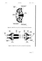
(fig. 373, fold-out 2)
(1) The torque converter consists
mainly of three cast aluminum elements:
pump assembly 82, stator assembly 94 and
turbine assembly 79. These, and related
minor components, are enclosed and sup-
ported by the input transfer housing 126
and converter housing 31 (fig. 374, fold-
out 3).
(2) Pump assembly 82 (fig. 373,
fold-out 2) has radial vanes cast into one
side surface. It is machined at the center
and bolted to a steel hub 88. The hub is
supported by a single-row ball bearing 91
which, in turn, is mounted on a stationary
ground sleeve 26 (fig. 374, fold-out 3).
The ground sleeve is rigidly mounted in
converter housing 31. The outside diam-
eter of pump assembly 82 (fig. 373, fold-
out 2) is bolted to converter cover assem-
bly 68.
(3)
The
stator
assembly
is
a
vaned reaction member. It includes stator
94, freewheel race 101, freewheel bearings
97, springs 98, cam 99 and various minor
components. This assembly mounts on the
splined outside diameter of the ground
sleeve 26 (fig. 374, fold-out 3). The stator
can freewheel in the direction of conver-
ter rotation but will lock up if an attempt
is made to rotate it in the opposite direc-
tion.
(4) Turbine assembly 79 (fig. 373,
fold-out 2) is a vaned casting similar to
pump assembly 82. It is riveted to a steel
hub which has internal splines which en-
gage turbine shaft 2 (fig. 375, fold-out 4).
A single-row ball bearing 73 (fig. 373,
11
Back to Top


