TM-9-2520-234-35 - Page 73 of 323
PAR
38-3 9
OPERATION OF HYDRAULIC SYSTEM S
CHAP
2,
SEC
I V
relay valve, where it is sent to the right-gear-
ed
steer
clutch,
through
the
geared
steer
coolant line.
(5) The right-geared steer clutch is ex-
hausted, after use, through the ball check
valve (upper) located between the steer feed
and steer coolant feed lines.
(6) In right steer in third gear, the
right-drive clutch (output clutch) is released,
the right-geared steer clutch is engaged and
supplied with coolant, and the left-drive clutch
(output clutch) is engaged and continues to
drive .
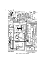
b . Fourth Gear, Full-left Steer (fig. 16)
Note . Refer to par. 56 and fig. 32
for the torque path through the power
train.
(1) The hydraulic system will function
in fourth gear steer in the same manner as
described for fourth gear straight travel in
par. 34, above, except for the position of the
steer valves and the flow of oil to the drive
clutches and steer clutches.
(2) In left steer, the steer control shaft
is rotated counterclockwise. This rotatio n
moves the right-steer valve upward while the
left-steer valve moves downward. Flow to the
left-drive clutch (output clutch) is blocked. A
regulated steer feed pressure is sent to the
steer relay valve. The steer relay valve sends
oil to the left-geared steer clutch, through the
left-geared steer clutch apply line.
(3) The flow to the right-drive clutch
(output clutch) is not interrupted and the clutch
continues to drive the right output. The right-
steer valve supplies steer coolant feed to left-
geared steer clutch.
The left-geared steer
clutch apply pressure can exhaust through the
lower check valve (between steer feed and
steer coolant feed lines) and the geared steer
coolant line, when application of steer is dis-
continued.
39. HYDRAULIC SYSTEM FUNCTION -
REVERSE RANGE, STEER
a. Reverse 1 Gear, Full-right Steer
—
(fig. 17)
Note. Refer to par. 57 and fig. 33
for the torque path through the power
train.
(1) The hydraulic system will function
in reverse 1-gear steer in the same manner
as described for reverse l-gear straight travel
in par. 35, above, except for the position of
the steer valves and the flow of oil to the drive
clutches and brakes.
(2) Refer to par. 37a(2) through (5) ,
above, for an explanation of the function of the
steer valves and oil flow to the drive clutches
and brakes.
(3) In reverse 1 gear, right steer, the
right-drive clutch (geared steer clutch) is re-
leased, the right brake is applied and supplied
with coolant, and the left-drive clutch (geared
steer clutch) continues to drive the left-output.
b. Reverse 2 Gear, Full-left Steer
—
(fig. 18)
Note . Refer to par. 58 and fig. 34
for the torque path through the power
train.
(1) The hydraulic system will functioning
reverse 2-gear steer in the same manner as
described for reverse 2-gear straight travel
in par. 36, above, except for the position of
the
steer
valves
and
oil
flow
to
the
drive
clutches (output clutches) and geared steer
clutches.
(2) Refer to par. 38b(2) and (3), above,
for an explanation of the function of the steer
valves and oil flow to the drive clutches and
geared steer clutches.
(3) In reverse 2 gear, left steer, the
left-drive clutch (output clutch) is released,
the left-geared steer clutch is applied and sup-
plied with coolant, and the right-drive clutch
continues to drive the right output.
4 3
Back to Top


