TM-9-2520-238-34 - Page 288 of 319
TM 9-2520-238-34
REPAIR HYDRAULIC MASTER BRAKE CYLINDER — Continued
0031 00
SET RELIEF VALVE PRESSURE
1.
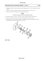
Install pressure gauge in output well of housing (1).
2.
Fill housing (1) with hydraulic fluid and install new gasket (18) and filler plug (19).
3.
Apply pressure at pushrod end and turn adjusting screw (15) until relief pressure is 100-130 psi (69-90 kPa).
4.
Remove pressure gage and drain hydraulic fluid from housing (1).
5.
Install new gasket (20) and vent plug (21) on relief valve (9).
6.
Install new protection bellows (22) on housing (1).
7.
Install instruction plate (23) on vent plug (21) with new lockwire (24).
0031 00-8
Back to Top


