TM-9-2520-246-34-1 - Page 196 of 418
TM 9-2520-246-34-1
b.
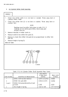
Air Cylinder Shifter Shaft Assembly.
FRAME 1
1.
Check that shifter shaft (1) is not bent or cracked. Throw away bent or
cracked shifter shaft.
2.
Check that shifter fork (2) is not bent or cracked. Throw away bent or
cracked fork.
NOTE
Readings must be within limits given in table 2-16. If
readings are not within given limits, throw away part
and get a new one.
3.
Measure diameter of shifter shaft (1).
4.
Measure width of two shifter fork pads (3).
5.
Measure to check that shifter fork pads (3) are perpendicular to shifter fork
bore (4).
6.
Measure height of spring (5).
END OF TASK
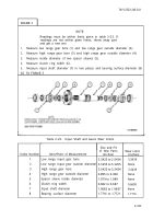
Table 2-16. Air Cylinder Shifter Shaft Assembly Wear Limits
Index Number
1
3
3 and 4
5
Item/Point of Measurement
Shifter shaft outside diameter
Shifter fork pad width
Shifter fork perpendicularity of pad
to bore
Free height of spring
Size and Fit
of New Parts
(inches)
0.8715 to 0.8725
0.562 to 0.572
0.005
2.64 to 2.85
Wear Limit
(inches)
0.8685
0.5550
0.030
2.55 minimum
2-176
Back to Top


