TM-9-2520-246-34 - Page 18 of 153
TM 9-2520-246-34
CHAPTER 2
DIRECT SUPPORT AND GENERAL SUPPORT
MAINTENANCE INSTRUCTIONS
Section I. REPAIR PARTS, SPECIAL TOOLS, AND EQUIPMENT
2-1. General.
Tools, equipment, and repair parts,
over and above those available to the using
organization, are supplied to direct support and
general support maintenance shops for maintaining,
repairing, and/ or rebuilding the material.
2-2. Repair Parts.
Repair parts required for the
maintenance of the transmissions, transfers, and
power takeoffs are listed in TM 9-2520-246-34P,
which is the authority for requesting or ordering
replacement parts.
2-3. Special Tools and Equipment.
The special
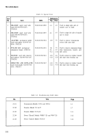
tools and equipment, tabulated in table 2-1, are listed
and illustrated in TM 9-2520-246-34P which is the
authority for requisitioning. Table 2-1 lists only the
special tools and equipment necessary to perform the
direct support, general support, and field maintenance
operations described in this technical manual. Table 2-
1 is included for information purposes only, and is not
to be used as a basis for requisitioning.
2-4. Common Tools and Equipment.
Standard
and commonly used tools having general application
to this material are listed in DA Supply Manuals SC
4910-95-CL-A01, A02, A50, A63, A64, A65, A67,
A68, A69, A72, A73, and A74, SC 5180-90-CL-N23,
SC 4910-95-CL-A31 and A32.
Section Il. TROUBLESHOOTING
2-5. General.
a. Purpose.
The information in this section is for
the use of support personnel in conjunction with, and
supplemental to the troubleshooting section in the
pertinent Organizational Maintenance Manual (TM 9-
2320-209-20/1). This information therefore provides
the continuation of instructions in the Organizational
Manual wherein a reference is made to direct support
and general support maintenance personnel for
corrective action.
b. Operation.
Operation of a transmission, transfer,
or power takeoff without a preliminary examination
can cause further damage to the components and
possible injury to personnel. Required inspection and
troubleshooting will eliminate further damage to
equipment and injury to personnel. Causes of faulty
operation in a unit or component can often be
determined without extensive disassembly.
c. lnspection.
Inspection after the component is
removed from the vehicle is performed to verify the
diagnosis made while the component was installed in
the vehicle, to uncover further defects or to determine
malfunctions if the unit or component alone is
received by the support organization. This inspection
is particularly important in the final case because it is
often the only means of determining the malfunction
without completely disassembling the component.
Refer to Chapter 2, section III for general cleaning,
inspection, and repair procedures.
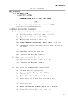
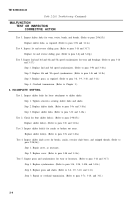
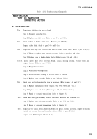
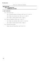
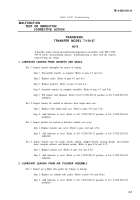
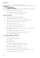
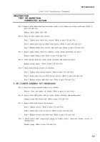
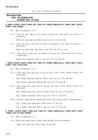
2-6. Introductory Information.
a.
This section contains troubleshooting
information for locating and correcting most of the
operating troubles which may develop in the
transmission models 3052 and 3053A, transfer models
T-136-27 and T-136-21, and power takeoff models
WN-7-28, WND-7-28, and P-136-C. Each malfunction
for an individual component unit or system is
followed by a list of tests or inspections which will
help you to determine corrective actions to take. You
should perform the tests/inspections and corrective
actions in the order listed.
b.
This manual cannot list all malfunctions that
may occur, nor all tests or inspections and corrective
actions. If a malfunction is not listed or is not
corrected by listed corrective actions, notify your
supervisor.
c.
The table lists the common malfunctions which
you may find during the maintenance of the
transmission models 3052 and 3053A, transfer models
T-136-21 and T-136-27, and power takeoff models
WN-7-28, WND-7-28, and P-136-C or their
components. You should perform the tests/inspections
and corrective actions in the order listed.
2-1
Back to Top

