TM-9-2520-246-34 - Page 8 of 153
TM 9-2520-246-34
Figure
3-38.
3-39.
3-40.
3-41.
3-42.
3-43.
3-44.
3-45.
3-46.
3-47.
3-48.
3-49.
3-50.
4-1.
4-2.
4-3.
4-4.
4-5.
4-6.
4-7.
4-8.
4-9.
4-10.
4-11.
4-12.
4-13.
4-14.
4-15.
4-16.
4-17.
4-18.
4-19.
4-20.
4-21.
4-22.
4-23.
4-24.
4-25.
4-26.
4-27.
4-28.
4-29.
4-30.
4-31.
4-32.
4-33.
iv
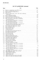
LIST OF ILLUSTRATIONS (Continued)
Title
Page
Removal of countershaft drive gear (fifth-speed gear) . . . . . . . . . . . . . . . . . . . . . . . . . . . . . . . . . . . . . . . . . . 3-17
Removal of countershaft fourth-speed gear. . . . . . . . . . . . . . . . . . . . . . . . .
. . . . . . . . . . . . . . . . . . . . . . . . . . 3-17
Removal of mainshaft rear bearing cap oil seal . . . . . . . . . . . . . . . . . . . . . . . . . . . . . . . . . . . . . . . . . . . . . . . .3-17
Shifter shaft cover . . . . . . . . . . . . . . . .
. . . . . . . . . . . . . . . . . . . . . . . . . . . . . . . . . . . . . . . . . . . . . . . . . . . . . . . 3-18
Removal of expansion plugs, setscrews, shifter shafts, actuating lug,
and shifter forks . . . . . . . . . . . . . . . . . . . . . . . . . . . . . . . . . . . . . . . . . . . . . . . . . . . . . . . . . . . . . . . . . . . . . . . . . . . . . . .3-18
Removal of poppet balls and springs . . . . . . . . . . . . . . . . . . . . . . . . . . . . . . . . . . . . . . . . . . . . . . . . . . . . . . . . .3-18
Removal of interlock plate and springs . . . . . . . . . . . . . . . . . . . . . . . . . . . . . . . . . . . . . . . . . . . . . . . . . . . . . . .3-18
Removal of first and reverse shifter shaft oil seal . . . . . . . . . . . . . . . . . . . . . . . . . . . . . . . . . . . . . . . . . . . . . . .3-19
Removal of lower shift lever, lever spring, and spring cap . . . . . . . . . . . . . . . . . . . . . . . . . . . . . . . . . . . . . . .3-19
Repair and replacement standard points of measurement
for input shaft and bearing . . . . . . . . . . . . . . . . . . . . . . . . . . . . . . . . . . . . . . . . . . . . . . . . . . . . . . . . . . . . . . . .3-22
Repair and replacement standard points of measurement
for transmission mainshaft assembly . . . . . . . . . . . . . . . . . . . . . . . . . . . . . . . . . . . . . . . . . . . . . . . . . . . . . . .3-23
Repair and replacement standard points of measurement
for transmission countershaft and gears . . . . . . . . . . . . . . . . . . . . . . . . . . . . . . . . . . . . . . . . . . . . . . . . . . . . .3-24
Repair and replacement standard points of measurement for
transmission, reverse idler gear and shaft assembly . . . . . . . . . . . . . . . . . . . . . . . . . . . . . . . . . . . . . . . . . .3-25
Positive locking transfer model T-136-27 - front view . . . . . . . . . . . . . . . . . . . . . . . . . . . . . . . . . . . . . . . . . . .4-1
Positive locking transfer model T-136-27 - rear view . . . . . . . . . . . . . . . . . . . . . . . . . . . . . . . . . . . . . . . . . . . .4-2
Removal of handbrake assembly . . . . . . . . . . . . . . . . . . . . . . . . . . . . . . . . . . . . . . . . . . . . . . . . . . . . . . . . . . . . .4-3
Transfer mounted on stand . . . . . . . . . . . . . . . . . . . . . . . . . . . . . . . . . . . . . . . . . . . . . . . . . . . . . . . . . . . . . . . . .4-4
Companion flange removal
4-4
. . . . . . . . . . . . . . . . . . . . . . . . . . . . . . . . . . . . . . . . . . . . . . . . . . . . . . . . . . . . . .
Air cylinder disassembly . . . . . . . . . . . . . . . . . . . . . . . . . . . . . . . . . . . . . . . . . . . . . . . . . . . . . . . . . . . . . . . . . . . .4-4
Front output shaft case and input shaft bearing cover . . . . . . . . . . .
. . . . . . . . . . . . . . . . . . . . . . . . . . . . . . .
4-4
Front output shaft and shifter assembly . . . . . . . . . . . . . . . . . . . . . . . . . . . . . . . . . . . . . . . . . . . . . . . . . . . . . .4-5
Front output clutch and case cover . . . . . . . . . . . . . . . . . . . . . . . . . . . . . . . . . . . . . . . . . . . . . . . . . . . . . . . . . .4-5
Rear output shaft assembly . . . . . . . . . . . . . . . . . . . . . . . . . . . . . . . . . . . . . . . . . . . . . . . . . . . . . . . . . . . . . . . . .4-5
Top cover and shifter shaft . . . . . . . . . . . . . . . . . . . . . . . . . . . . . . . . . . . . . . . . . . . . . . . . . . . . . . . . . . . . . . . . .4-5
Bearing covers and case plug.
.. . . . . . . . . . . . . . . . . . . . . . . . . . . . . . . . . . . . . . . . . . . . . . . . . . . . . . . . . . . . . .4-6
Shifter fork, input shaft, and countershaft . . . . . . . . . . . . . . . . . . . . . . . . . . . . . . . . . . . . . . . . . . . . . . . . . . . .4-7
Rear output shaft disassembly-exploded view . . . . . . . . . . . . . . . . . . . . . . . . . . . . . . . . . . . . . . . . . . . . . . . .4-7
Countershaft disassembly-exploded view . . . . . . . . . . . . . . . . . . . . . . . . . . . . . . . . . . . . . . . . . . . . . . . . . . . . .4-8
Input shaft disassembly-exploded view . . . . . . . . . . . . . . . . . . . . . . . . . . . . . . . . . . . . . . . . . . . . . . . . . . . . . .4-8
Transfer case cover disassembly . . . . . . . . . . . . . . . . . . . . . . . . . . . . . . . . . . . . . . . . . . . . . . . . . . . . . . . . . . . . .4-9
Remover and replacer with handle . . . . . . . . . . . . . . . . . . . .
Front output shaft cover disassembly . . . . . . . . . . . . . . . . . .
Transfer case disassembly . . . . . . . . . . . . . . . . . . . . . . . . . . . .
Disassembly of handbrake shoe assembly . . . . . . . . . . . . . .
Repair and replacement standard points of measurement
for transfer gear train . . . . . . . . . . . . . . . . . . . . . . . . . . . . .
Repair and replacement standard points of measurement
for transfer shafts and bearings . . . . . . . . . . . . . . . . . . . . .
Repair and replacement standard points of measurement
for transfer output shaft and cover . . . . . . . . . . . . . . . . . .
Repair and replacement standard points of measurement
for transfer case and seals . . . . . . . . . . . . . . . . . . . . . . . . . .
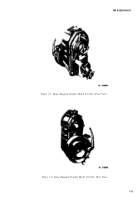
Sprag equipped transfer model T-136-21 - front view. . . .
Sprag equipped transfer model T-136-21 - rear view. . . . .
4-9
. . . . . . . . . . . . . . .
. . . . . . . . . . . . . . . . . . . . . . . .
4-10
. . . . . . . . . . . . . . . . . . . . . . . . . . . . . . . . . . . .
4-10
. . . . . . . . . . . . . . . . . . . . . . . . . . . . . . . . . . .
4-10
. . . . . . . . . . . . . . . . . . . . . . . . . . . . . . . . . . . . . .
. . . . . . . . . . . . . . . . . . . . . . . . . . . . . . . . . . . . . . .
4-13
. . . . . . . . . . . . . . . . . . . . . . . . . . . . . . . . . . . . . . . . .
4-15
. . . . . . . . . . . . . . . . . . . . . . . . . . . . . . . . . . . . . .
4-17
4-18
. . . . . . . . . . . . . . . . . . . . . . . . . . . . . . . . . . . . . . .
. . . . . . .4-19
. . . . . . . . . . . . . . . . . . . . . . . . . . . . . . . .
4-20
. . . . . . . . . . . . . . . . . . . . . . . . . . . . . . . . . . . . . . .
4-21
. . . . . . . . . . . . . . . . . . . . .
. . . . . . . . . . . . . . . . . . .
Removal of handbrake assembly . . . . . . . . . . . . . . . . . . . . . .
Transfer mounted on overhaul stand . . . . . . . . . . . . . . . . . . . . . . . . . . . . . . . . . . . . . . . . . . . . . . . . . . . . . . . . . 4-22
Companion flanges-removal. . . . . . . . . . . . . . . . . . . . . . . . . . . . . . . . . . . . . . . . . . . . . . . . . . . . . . . . . . . . . . .4-22
Removal of transfer covers. . . . . . . . . . . . . . . . . . . . . . . . . . . . . . . . . . . . . . . . . . . . . . . . . . . . . . . . . . . . . . . . . .4-22
Removal of front output shaft and reverse shift assembly . . . . . . . . . . . . . . . . . . . . . . . . . . . . . . . . . . . . . . .4-23
Removal of rear output, idler, and input shaft assemblies . . . . . . . . . . . . . . . . . . . . . . . . . . . . . . . . . . . . . . .4-23
Back to Top

