TM-9-2520-272-34P - Page 79 of 488
TM 9-2520-272-34&P
4-6. INSTALL TRANSMISSION ON MAINTENANCE STAND
10
11
12
13
14
15
16
17
18
(SHEET 6 OF 7)
WARNING
When rotating transmission vertical to
horizontal position, weight of transmission
is transferred from one
S
ling to the other.
When the center of gravity shifts,
transmission may suddenly tilt, thrusting
heavy momentary stress on sling and hoist.
To avoid injury or death, keep out from
under and clear of transmission at all times.
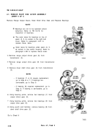
Raise two-legged sling as necessary to maintain proper
clearance between transmission and floor
Slowly raise three-legged sling until weight of
transmission is entirely on three-legged sling.
Remove two-legged sling.
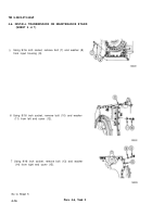
Rotate adapter plate (18) on maintenance stand to
match hole pattern in plate with holes on bottom of
transmission (19).
Using aligning punch hoist, and rotational control on
maintenance stand, align holes in bottom of
transmission (19) with holes in adapter plate (18).
Install washers (20) under heads of three 1/2-32 x 2
inch bolts (21). Using 3/4 inch socket, install bolts
through three holes in adapter plate (18). Screw bolts
into holes on bottom of transmission (19).
Using torque wrench, tighten bolts (21) to 80-95 lb-ft
(108-129 N•m).
Using 9/16 socket, remove three 3/8-16 x 1-3/4 inch
bolts (16) and six washers (17) holding three-legged
sling.
Remove three-legged sling.
Go to Sheet 7
4-18
Para. 4-6, Task 2
Back to Top

