TM-9-2540-207-14-P - Page 12 of 288
TM 9-2540-207-14&P
x
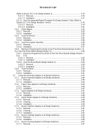
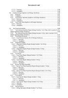
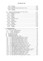
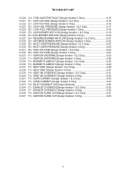
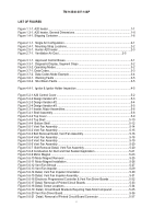
LIST OF FIGURES
Figure 1.1-1. A20 heater.
...........................................................................................................
1-1
Figure 1.3-1. A20 heater, General Dimensions .
........................................................................
1-6
Figure 1.4-1. Shipping Container.
..............................................................................................
1-6
Figure 2.1-1.
Single Air Configuration.
......................................................................................
2-1
Figure 2.4-1.
Mounting Strap Locations.
...................................................................................
2-2
Figure 2.5-1.
Hunter A20 heater .
..............................................................................................
2-3
Figure 2.7-1.
Ventilation Air Duct.
.................................................................................
2-5
Figure 3.1-1.
Approved Control Boxes.
.....................................................................................
3-1
Figure 3.3-1.
Diagnostic Display, Segment Steps .
...................................................................
3-2
Figure 3.3-2. Operating Modes.
.................................................................................................
3-2
Figure 3.7-1. Data Codes.
..........................................................................................................
3-3
Figure 3.7-2.
Data Codes Mode Example.
................................................................................
3-4
Figure 3.8-1.
Warning Faults .
...................................................................................................
3-5
Figure 3.8-2.
Shut Down Faults .
...............................................................................................
3-5
Figure 4.4-1.
Ignitor & Ignitor Holder Inspection .
......................................................................
4-5
Figure 5.2-1 A20 Control Cover.
................................................................................................
5-2
Figure 5.2-2 Design Iteration #1 .
...............................................................................................
5-3
Figure 5.2-3 Design Iteration #2 .
...............................................................................................
5-4
Figure 5.2-4 Design Iteration #3 .
...............................................................................................
5-5
Figure 5.3-1 heater, Major Assemblies.
.....................................................................................
5-6
Figure 5.4-1 Shell Assembly.
.....................................................................................................
5-8
Figure 5.4-2 Top Cover.
.............................................................................................................
5-9
Figure 5.4-3 Top Shell .
............................................................................................................
5-10
Figure 5.4-4
Bottom Shell .
......................................................................................................
5-12
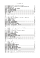
Figure 5.6-1 Vent Fan Assembly .
............................................................................................
5-14
Figure 5.6-2 Vent Fan Assembly .
............................................................................................
5-15
Figure 5.6-3 Bolt Removal Detail, Vent Fan Assembly.
...........................................................
5-16
Figure 5.6-4 Vent Fan Assembly .
............................................................................................
5-18
Figure 5.6-5 Vent Fan Assembly .
............................................................................................
5-19
Figure 5.6-6 Vent Fan Assembly .
............................................................................................
5-20
Figure 5.6-7
Bolt Removal Detail, Vent Fan Assembly.
..........................................................
5-20
Figure 5.6-8 Combustion Air Duct and Inlet Sealant Application.
............................................
5-21
Figure 5.6-9 Motor Magnet .
.....................................................................................................
5-23
Figure 5.6-10 Motor Magnet Removal .
....................................................................................
5-25
Figure 5.6-11 Motor Magnet Installation .
.................................................................................
5-26
Figure 5.6-12 Vent Fan Shroud .
..............................................................................................
5-27
Figure 5.6-13 Vent Fan Impeller .
.............................................................................................
5-29
Figure 5.6-14 Detail, Vent Fan Impeller Orientation .
...............................................................
5-30
Figure 5.6-15 Detail, Vent Fan Impeller Assembly .
.................................................................
5-31
Figure 5.6-16 Electronic Programmed Controller & Vent Fan Driver Boards .
.........................
5-32
Figure 5.6-17 Detail, Removal of Printed Circuit Boards .
........................................................
5-33
Figure 5.6-18 Detail, Screw Locations.
....................................................................................
5-34
Figure 5.6-19
Detail, Circuit Board Brackets Requiring Heat-Sink Compound.
......................
5-35
Figure 5.6-20 Vent Fan Driver Board.
......................................................................................
5-36
Figure 5.6-21
Detail, Removal of Printed Circuit Board Connector .
.......................................
5-37
Back to Top


