TM-9-2540-207-14-P - Page 13 of 288
TM 9-2540-207-14&P
xi
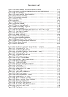
Figure 5.6-22 Detail, Vent Fan Driver Board Screw Locations .
...............................................
5-37
Figure 5.6-23 Detail, Circuit Board Brackets Requiring Heat-Sink Compound.
.......................
5-38
Figure 5.6-24
Vent Fan Motor.
................................................................................................
5-39
Figure 5.6-25 Detail, Vent Fan Motor Orientation.
...................................................................
5-41
Figure 5.7-1
Combustor Assembly .
........................................................................................
5-43
Figure 5.7-2
Combustor Assembly .
........................................................................................
5-44
Figure 5.7-3
Flame Tube .
.......................................................................................................
5-46
Figure 5.7-4
Ignitor.
.................................................................................................................
5-47
Figure 5.7-5 Ignitor Holder.
......................................................................................................
5-49
Figure 5.7-6
Burner Chamber.
................................................................................................
5-50
Figure 5.7-7
Burner Housing, Detail .
......................................................................................
5-52
Figure 5.7-8
Burner Cartridge Alignment.
...............................................................................
5-53
Figure 5.7-9
Burner Cartridge.
................................................................................................
5-54
Figure 5.7-10
New Burner Wick (left); 50% deteriorated Burner Wick (right) .
.......................
5-55
Figure 5.7-11
Fuel Shaft & Pushnut.
.......................................................................................
5-56
Figure 5.7-12
Burner Housing.
................................................................................................
5-57
Figure 5.7-13
Detail, Fuel Shaft.
.............................................................................................
5-58
Figure 5.8-1 Heat Exchanger Assembly .
.................................................................................
5-60
Figure 5.8-2
Heat Exchanger Assembly .
................................................................................
5-61
Figure 5.8-3 Exhaust Sensor Fitting Location.
.........................................................................
5-62
Figure 5.8-4 Heat Exchanger Assembly, Installation.
..............................................................
5-63
Figure 5.8-5 Vent Sensor Assembly .
.......................................................................................
5-65
Figure 5.8-6 Vent Outlet Seal .
.................................................................................................
5-67
Figure 5.9-1.
Top Housing Assembly (Design Iteration 1 & 2 Only) .
......................................
5-69
Figure 5.9-2.
Top Housing, Top View .
....................................................................................
5-70
Figure 5.9-3.
Top Housing, Bottom View.
...............................................................................
5-70
Figure 5.9-4.
Top Housing Assembly (Design Iteration 3 Only).
.............................................
5-71
Figure 5.9-5.
Top Housing, Top View .
....................................................................................
5-72
Figure 5.9-6.
Top Housing, Bottom View.
...............................................................................
5-72
Figure 5.9-7.
Fuel Pressure Sensor.
.......................................................................................
5-73
Figure 5.9-8. J4 Logic Connector detail.
..................................................................................
5-74
Figure 5.9-9. Removal of Fuel Pressure Sensor.
.....................................................................
5-74
Figure 5.9-10.
Diagnostic Display.
..........................................................................................
5-75
Figure 5.9-11.
Diagnostic Display.
..........................................................................................
5-77
Figure 5.9-12. Diagnostic Display Board Details .
....................................................................
5-78
Figure 5.9-13.
Fuel Pump .
......................................................................................................
5-79
Figure 5.9-14. Fuel Pump Hoses.
............................................................................................
5-80
Figure 5.9-15. Installing New Fuel LInes .
................................................................................
5-81
Figure 5.9-16.
Fuel Pump .
......................................................................................................
5-82
Figure 5.9-17. Fuel Pump Connector J4.
.................................................................................
5-83
Figure 5.9-18. Fuel Pump Hoses.
............................................................................................
5-84
Figure 5.9-19. Fuel Pump Mounting Screws.
...........................................................................
5-85
Figure 5.9-20. Installing New Fuel Lines.
.................................................................................
5-86
Figure 5.9-21. Burner Fan Plate Assembly.
.............................................................................
5-87
Figure 5.9-22. Burner Fan Plate, Screw Locations.
.................................................................
5-88
Figure 5.9-23. Fuel Leak Check Points.
...................................................................................
5-90
Figure 5.9-24.
Burner Fan Plate Assembly.
............................................................................
5-91
Figure 5.9-25.
Burner Fan Plate, Screw Locations.
................................................................
5-92
Figure 5.9-26.
Fuel Leak Check Points.
..................................................................................
5-94
Figure 5.9-27. Fuel Injector.
.....................................................................................................
5-95
Back to Top

