TM-9-2815-200-35
ENGINE, WITH CONTAINER:TURBOSUPERCHARGED, DIESEL ,FUEL INJECTION ,90-DEGREE “V” TYPE, AIR - COOLED ,12 - CYLINDER , ASSEMBLY ;MODELS AVDS-1790-2M (2815-856-4996), AVDS-1790-2A AND AVDS-1790-2AM (2815-856-9005)
TECHNICAL MANUAL; DIRECT SUPPORT, GENERAL SUPPORT AND DEPOT MAINTENANCE MANUAL INCLUDING REPAIR PARTS AND SPECIAL TOOLS LISTS
TM-9-2815-200-35 - Page 364 of 779
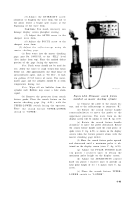
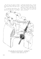
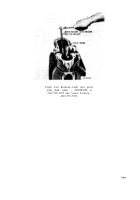
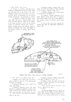
Figure 6-63.
(2)
Valve seats.
Replace cylinder assembly
which do not show perfect contact with valve
(41, fig. B-4) when inserts do not fit securely in
face. Grind inserts (fig. 6-63) as described in (a)
the cylinder. Grind seats which do not show
through (e), below.
perfect contact with valve face. Grind seats
(a) A
45
degree angle grinding stone must
c.
Honing Specifications.
(Part No .
be used to grind valve seat inserts.
(b) Dress seat on the insert with stone,
using valve seat grinding machine.
(c) After dressing seat of insert, check
valve contact as described in paragraph 6-31b.
(d) When perfect contact is obtained,
narrow seat on insert to width specified in figure
6-63 by grinding inner wall and exposed face of
insert to the angles specified.
(e) Keep valve seat area as near a s
possible to center of valve face. Valves should
never seat at the top or bottom of the valve face
area.
b. Cylinder Bore.
Replace cylinder assembly
when joint between cylinder head and cylinder
barrel is pitted or eroded. Replace cylinder
assembly when cylinder bore dimensions are not
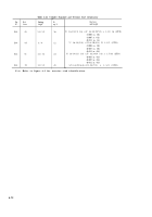
within limits specified in the overhaul standards
(table 6-15), or when average dome en d
measurement is larger than average flange end
measurement. Reanodize head if required. Hone
cylinder to remove scratches, scoring or ring
ridge. Hone cylinder when out-of-round mor e
than 0.003 in. Hone cylinders as described in c
and d, below.
10865297, FSN 2815-765-9711 cylinder only)
(1) Cross hatch angle to be 35 degrees off
the horizontal.
(2) Cross hatch to be cut uniformly in both
directions.
(3) Cross hatch to be clean-cut, but not
sharp, and free from torn or folded metal.
(4) The micro-finish roughness shoul d
average between 35 and 45 micro-inches, rms
(root mean square deviation from the mean), as
measured on the profilometer machin e
(Micrometrical Mfg. Company, Ann Arbor ,
Michigan, Type QA, Type V Moto-Trace or
equivalent).
(5) The plateau area should be 1 / 2 to 2 / 3
of the surface area.
(6) The plateau should be free from bur-
nished or glazed surface.
(7) The surface is to be free of imbedded
particles.
d. Honing Recommendations.
(Part No .
10865297, FSN 2815-765-9711 cylinder only)
(1) Honing stones should be Army Nos.
11662775-1 and 11662775-2 used alternately
around the honing head. The stones are ap-
6-70
Back to Top


