TM-9-2815-202-34 - Page 356 of 670
TM9-2815-202-34
4-42. GOVERNOR REPAIR
This task covers:
a. Disassembly
b. Cleaning/Inspection
c. Assembly
INITIAL SETUP
MODELS
7083-7395 7083-7398
TOOLS AND SPECIAL TOOLS
General mechanics tool kit (App B, Item 96)
Governor cover bushing remover
(App B, Item 78)
Governor cover bearing installer (App B, Item 77)
Governor cover bushing installer
(App B, Item 53)
Torque wrench (App B, Item 101)
MANDATORY REPLACEMENT PARTS
1 Seal ring (App F, Item 131)
1 Seal ring (App F, Item 132)
2 Lockwashers (App F, Item 92)
2 Gaskets (App F, Item 78)
1 Seal ring (App F,ltem 135)
1 Gasket (App F,ltem 82)
1 Key washer (App F, Item 165)
1 Expansion plug (App F, Item 113)
EXPENDABLE/DURABLE SUPPLIES
Grease (App C, Item 22)
Sealant (App C, Item 40)
Engine oil (App C, Item 16)
Cleaning solvent (App C, Item10)
Bolt 5/1 6-24 x 3 (App C, Item 4)
Sealant (App C, Item 38)
EQUIPMENT CONDITION
Para Description
4-17 Throttle control rods removed
4-18 Governor removed from blower
a. Disassembly
●
●
NOTE
Before and during disassembly of
governor, clean entire unit and
visually inspect for worn or
damaged parts which may be
repaired or replaced without
complete disassembly.
If remote control levers are on
governor cover, remove prior to
disassembly of cover.
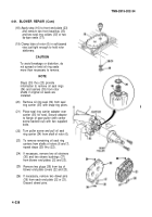
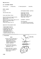
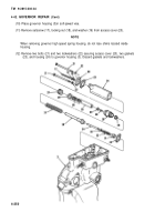
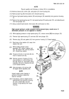
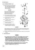
(1) Remove eight bolts (1) securing
governor cover (2) to governor (3).
Remove cover and gasket (4).
Discard gasket.
4-248
Back to Top

